Close
0%
0%

Paw Pet

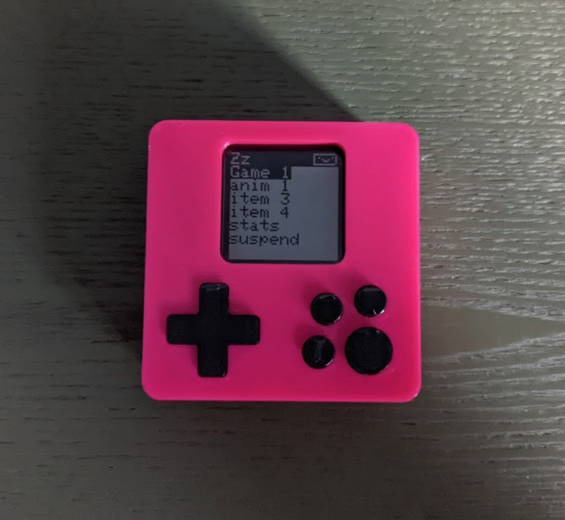
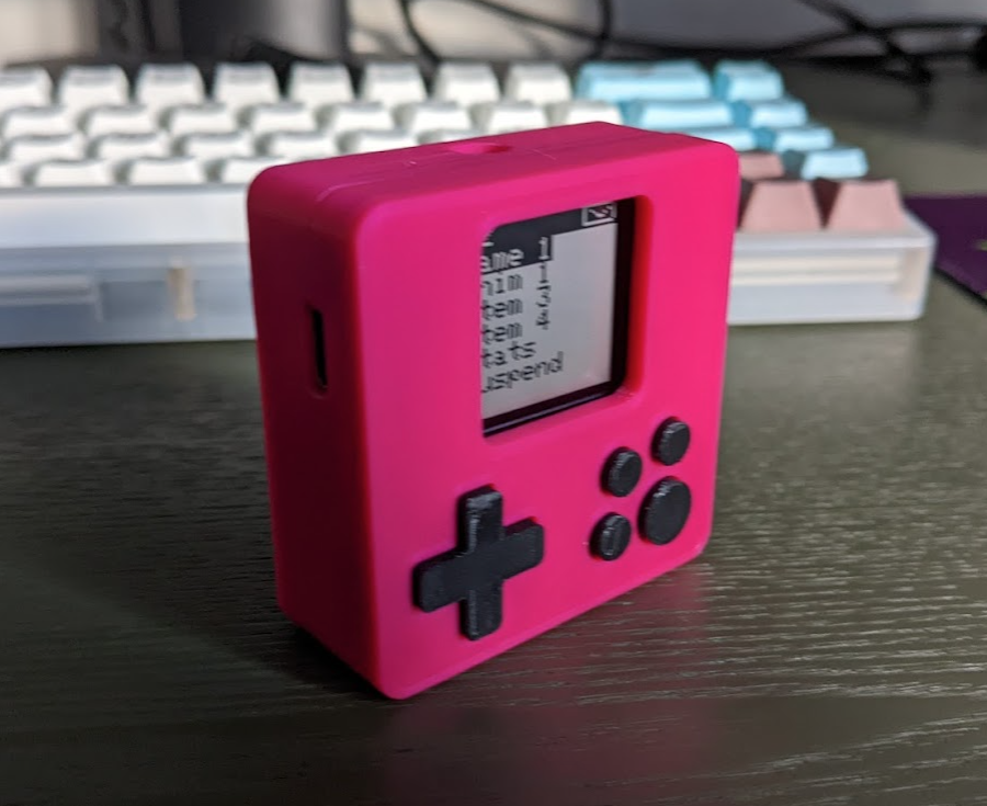
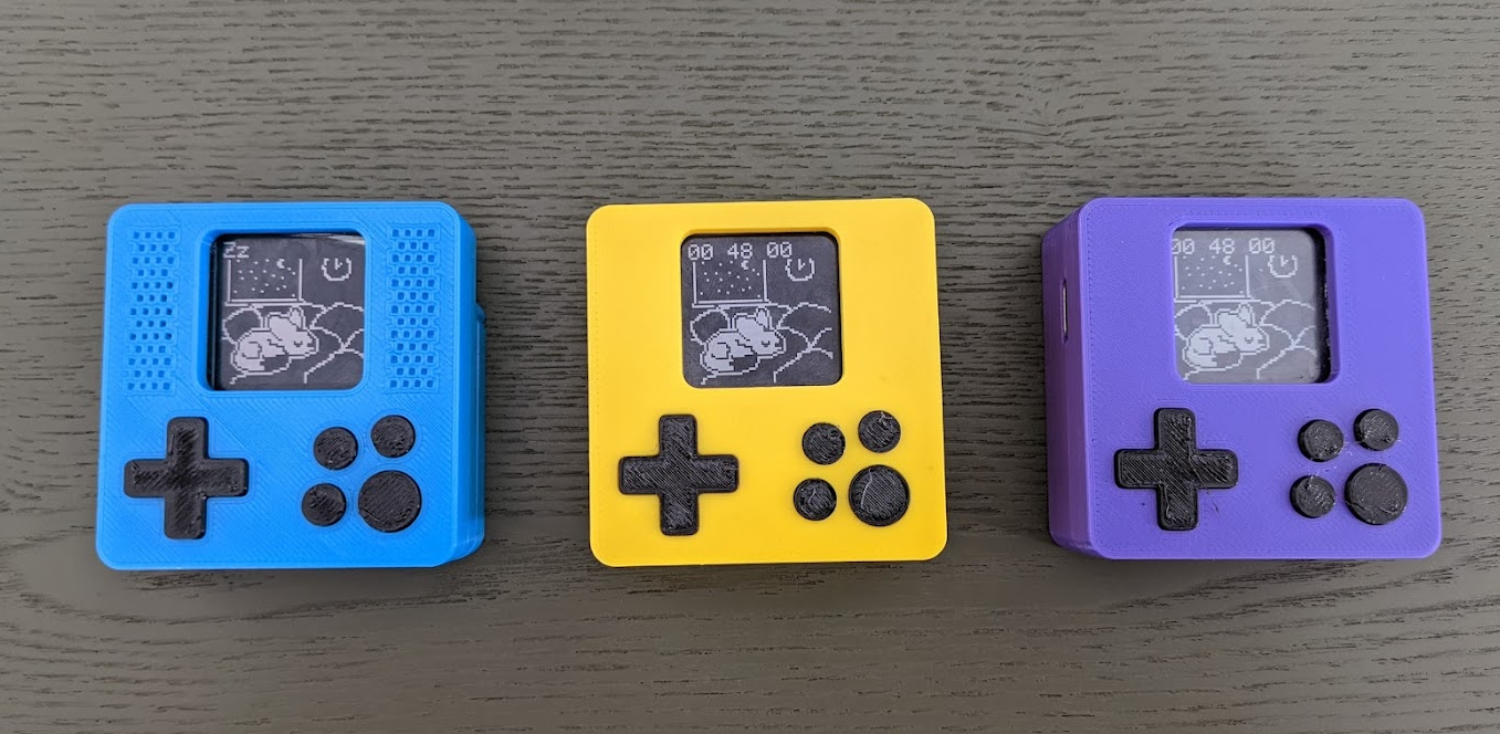
Pocketable digital pet using the ATSAMD21 and Sharp memory lcd for long battery life.

Similar projects worth following
Pocket sized digital pets are really cool but pretty rare these days. I thought it would be fun to make one.

Based on the ATSAMD21 chip, 128x128 sharp memory lcd, with 2MB of flash for graphics storage, the current design runs off of 2xAAA.

A digital pet with dedicated physical hardware would be heckin cool.

 
What features would make it extra cool?
- long battery life (multi week or even multi-month if possible, even better if rechargeable)

- relatively easy to make software for (via Arduino SDK or circuit/micro python)

- easy image transferring for adding new digital pets for non-technical users

- at least 2-10 fps screen for mini games

- buzzer/beeper/speaker for cool tunes (and lets the pet to yell at you when it needs digital food or attention)

- cheap, ideally less than 30, or 20 USD in parts


Current feature set:
- approx. two week battery life using 2xAAA (I think this can still be improved via software and new power regulator selection)

- currently uses Arduino SDK, the device is based off of the Adafruit feather m0 architecture, so in theory should be capable of running circuit python (no idea how this will affect battery life though, last I checked deep sleep was not supported on circuit python)

- device implements mass storage support for copying custom image files over

- sharp memory lcd with the samd21 allows for approx. 30 fps using DMA transfer

- piezo buzzer for simple tones 

- pre-pandemic BOM was about 20 USD each for producing a batch of 100

Current Status:
- Hardware finished! Small batch production started. Working on game and virtual pet logic, as well as lots of pixel art. 


Source, Models, Schematics on Github

pawsome-v8-prod-r1-pla.3mf

3mf - 221.50 kB - 02/16/2022 at 02:43

Download

pawpet.kicad_pcb

kicad_pcb - 292.10 kB - 02/16/2022 at 02:42

Download

pawpet.kicad_sch

kicad_sch - 162.58 kB - 02/16/2022 at 02:42

Download

  • 1 × ATSAMD21G18A 256kb flash, 32 kb ram, 48 mhz
  • 1 × LS013B7DH03 Sharp 128x128 FPC LCD 1.28"
  • 1 × USB4105-GF-A usb-c connector
  • 1 × PKMCS0909E4000 piezo buzzer
  • 8 × ‎EVQ-Q2K02W‎ smd d-pad and input buttons

View all 18 components

  • HELLO AGAIN

    NanoCodeBug06/14/2023 at 03:06 0 comments

    I am still working on this!
    Life events and such get in the way, and I've decided to rewrite the codebase in Rust using the atsamd-hal package for Rust embedded, for fun and to avoid the mess of arduino package dependencies.

    As a part of this, the code has been rewritten to be entirely stack allocated and uses the hf2 protocol for updating and uploading assets, with the goal of a new hf2 bootloader that will display update progress.

    The use of hf2 instead of simulated flash storage solves a lot of the compatibility issues I was having between mac/linux/windows.

    In general the sdk setup and build process is a lot simpler now, especially for the web build which uses wasm-pack instead of emscripten. 

    Feature parity between the two code bases is nearly present (only missing support for musical sequences), and I've moved on to making sprite assets again. The random reboots every couple days that were observed in the old code base have also ceased, though I never discovered the source.

  • First Fully Assembled non-debug PawPet

    NanoCodeBug02/13/2022 at 00:59 0 comments

    First fully assembled paw-pet with the final hardware and case design!
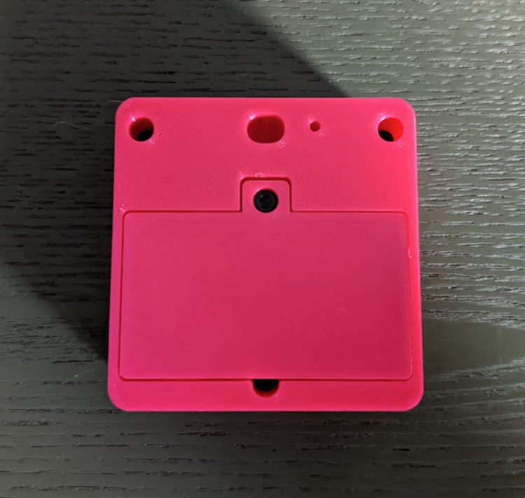
    Back has a hole for a lanyard/keychain, and a hole for a reset pin to the reset button. 
    Using filatech 40 filament for the buttons, which prints much cleaner compared to the previous flexible filament.

    Other major changes include using the TCC counter feature of the samd21 to generate a clock signal for the display at 30hz - even in standby. This puts it in spec for the screen according to the datasheet guidelines. 

    As well as successful operation down to 1.9v by disabling the brown out detection (BOD33) and increasing the flash wait states. Two Ni-MH cells won't reach that voltage, but Alkhaline can in theory. Without disabling BOD33 it shuts off at 2.1v, in theory this gives it a bit more battery life, allowing it maximize use of the battery cells. Below 1.9v the display no longer turns on, though the samd21 keeps running. 

    Refreshing the display at 30hz even while in standby was the last remaining hardware hurdle. With that working the focus will now entirely be in software and pixel art for the virtual pets.  

  • New case and small batch production

    NanoCodeBug01/27/2022 at 22:16 1 comment

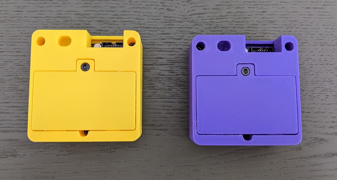
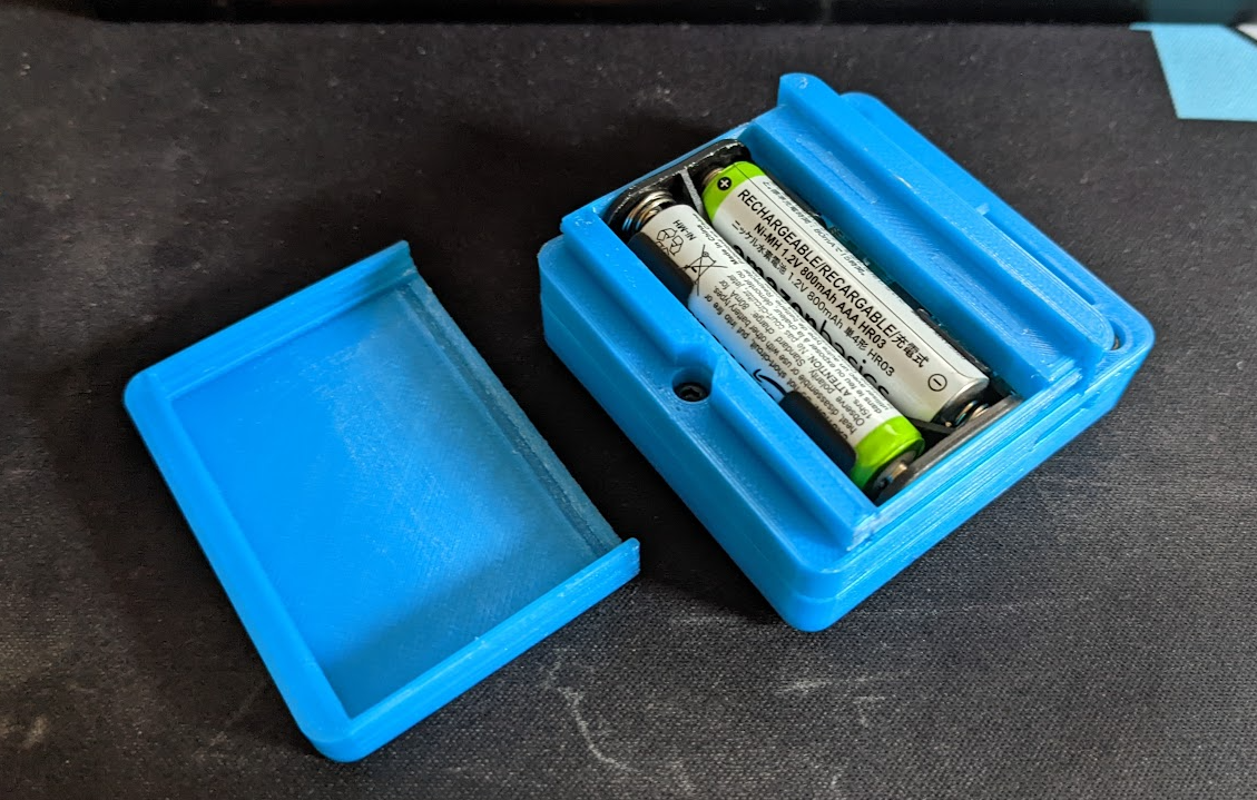
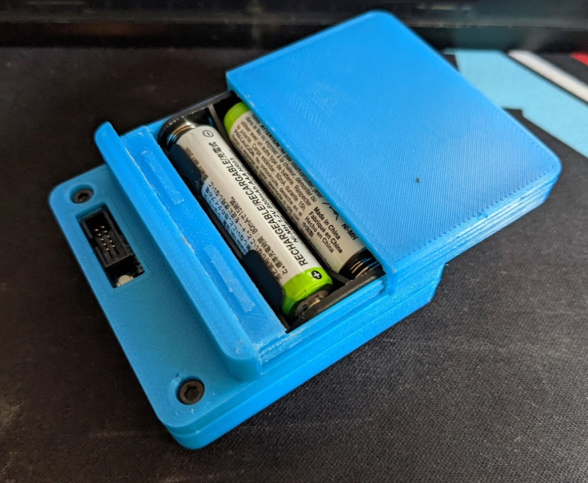
    I've updated the case design to have a screw battery door instead of a sliding one. The durability of the sliding one was not great, and the rails were causing the exterior case surface to have imperfections. The rails also required the orientation of the back piece to not be flat on the print bed, requiring extra finishing to remove the supports. The new design with a screw door into a heat set insert should be more durable, and results in much nicer print quality as pictured below.

    The lcd is now having its polarity refreshed at 60hz even in standby by mapping an internal clock to a external pin. Unforunately this is the slowest i can seem to do this, since the division factor against the internal 32khz oscillator only has "8 division bits" available. Which is somehow not a max divisor of 2^8 but 8. Leading to a division of (32000 / 2^( <divisor> + 1 )). For a max division of 512. To use a different internal clock divider with a larger divisor would require remapping pins and determining if the max divisor clock GLCK1 can be remapped - as its currently being mapped to the external oscillator for the core cpu clock. 

    I wonder if the TCC feature can be used to generate a 30hz clock for the display polarity? The 60hz one should be ok for now. I can visibly see the display blink in strong direct lighting on low battery, suggesting that the polarity change is still working at 60hz, even in standby. (whereas the previous design was only swapping polarity at 30 hz or slower and not all in standby)

    I've put in an order with OSHPark for a medium run of 30 boards, with a few final design changes:
    - replaced the debug port with a pogo pin connector for easy bootloader flashing
    - exposed a test point for the polarity clock signal on the display for easier probe attachment

    Also ordered some foaming tpu filament and ninjaflex chinchilla to experiment with nicer feeling buttons. The current ones don't print with a good finish and feel ok. Solid buttons click very loud, so finding a nice feeling rubber/tpu material would be great. 

  • Revision 6.4

    NanoCodeBug01/21/2022 at 04:22 0 comments

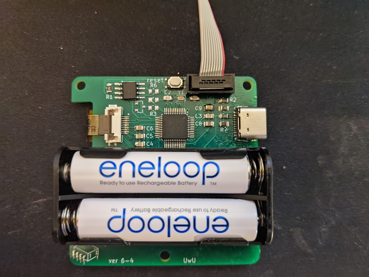
    Revision 6.4!

    usb-c for data transfer is working nicely, and I'm getting a lot better at hot air soldering! 

    Unfortunately, the mosfets I ordered were the wrong size (too small by a factor of like 3). TIL that sot-23 is not a size but a shape that can have different scales. This doesn't stop development or testing, but prevents the battery reading indicator and the new power saving around that from being tested for now. 

    When the correct sized mosfets arrive I'll assemble another for hooking up to the Current Ranger and see how standby current has changed.

    Also in this new revision, I've wired the display polarity refresh to the samd21. I'm going to experiment with mapping this directly to the internal clock with a divider to refresh it at somewhere between 1-30 hz. Then I can ignore keeping track of this in software during standby - in theory. The display supports switching polarity via SPI commands, but not both modes at the same time. 

  • Battery life optimizations

    NanoCodeBug12/18/2021 at 05:54 0 comments

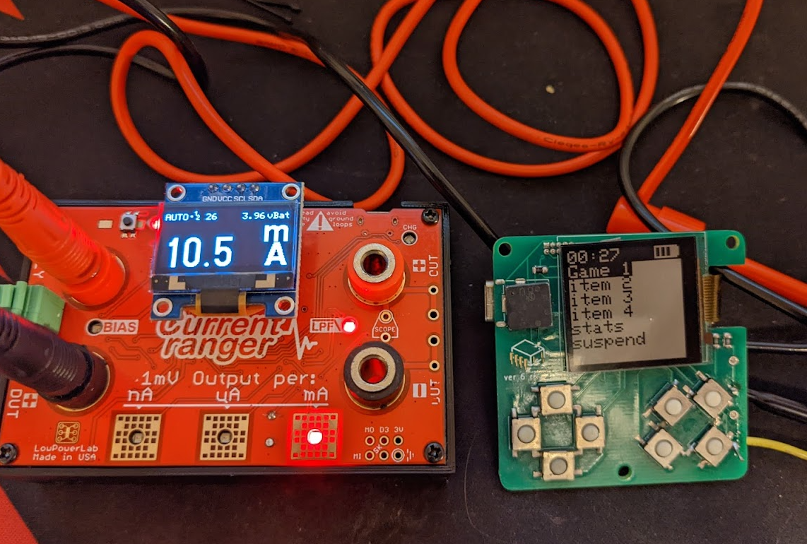
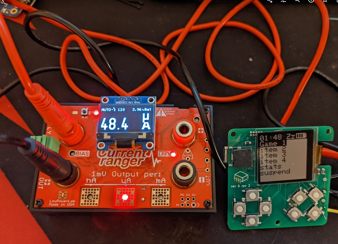
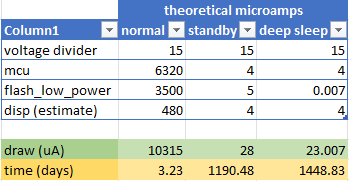
    Disabling the DAC and other unused timers and clock sources I've gotten the power consumption down from ~12 ma to ~10 ma while active, and to 50-70 ua while in sleep. The voltage divider is in theory taking 15-20 ua, making it toggleable with a mosfet will help with sleep power consumption, but given how much the active state takes, and how long the user is expected to playing it, say 30 minutes a day on average + the samd21 waking up every minute for updating the screen clock, optimizing for the sleep power draw further might not be worth it. (if the device stayed only in sleep mode total battery life is approx. 400+ days) 

    Various online power calculators for IoT devices suggest something near 60 days of total battery life with this on/off cycle. I'll have to validate that with experimental data. Reducing sleep current draw by 20u which the voltage divider is theoretically taking provides an additional ~2 days of usage or 3% more runtime.

    Active state:

    Sleep state:

  • New PCBs! New Problems T_T

    NanoCodeBug12/17/2021 at 05:09 0 comments

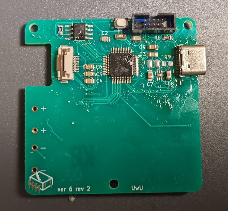
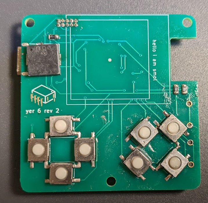
    New PCBs arrived! Just in time to assemble another prototype before the holidays. Still learning how to do SMD soldering with hot air. I cleaned up the PCBs later, but here it is almost complete. Feels like it's still easier to solder the larger chips with an iron than with hot air at the moment. Hot air makes getting the 805 sized parts a lot easier to seat nicely though. 


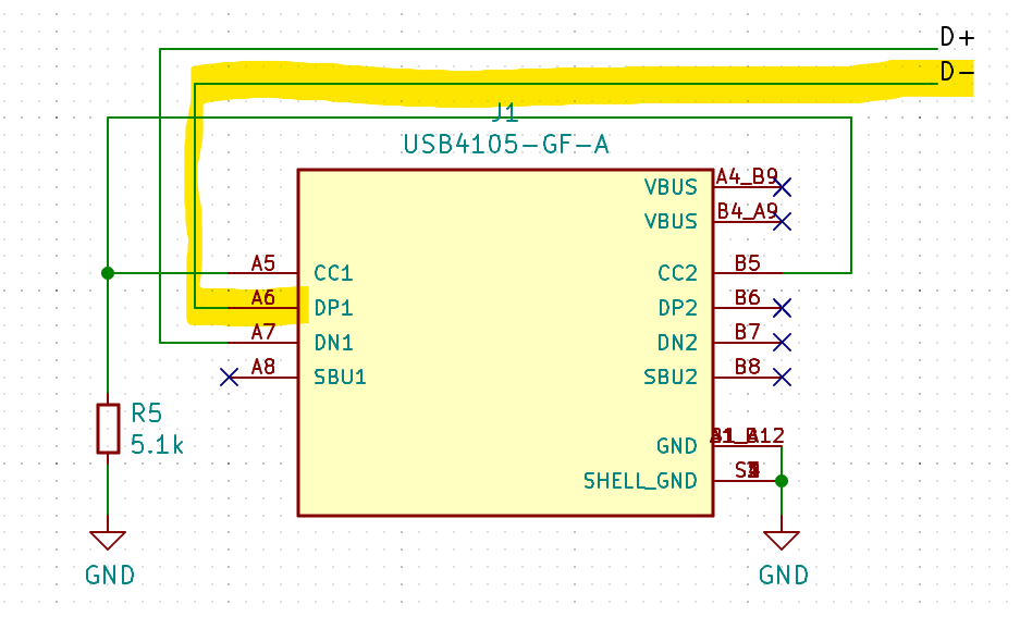
    Unfortunately, this board has a major flaw, highlighted below. I've accidentally flipped the data positive and data negative. Everything else works though! I won't be able to work with this prototype as a MSC device, but programming and debugging over jtag works fine. I'll remove the battery socket and add headers for attaching the CurrentRanger.

    Next revision will have the mosfet for toggling the voltage divider, as well as an updated usb-c circuit, to be more compliant with the detect lines both getting resistors, and the D1 and D2 lines being paired together. As well as a resistor to simulate load on the usb 5v line, for devices that refuse to start data communication unless power draw is detected.

  • Dropping boost converter, adding mosfet

    NanoCodeBug12/16/2021 at 03:00 0 comments

    After running some low power tests, it seems that the display will operate without issue down to 2.1v or so before the NiMH cells fully discharge. The boost-converter was primarily for driving a high enough voltage to the display, and optionally allowing for easier to source flash chips that operated on 2.6-3.3v logic. 

    In the past I observed flashing when the screen polarity is flipped, which the Adafruit provided library was doing every few refreshes, at 3.3v-5v VDD this polarity flip is not visible, but on lower voltages (as the battery discharges) the polarity flip update causes the screen to visibly clear and blink. Avoiding this polarity refresh during minigames can be solved in software, or potentially skipped entirely (the datasheet for the 128x128 version does not include documentation of this feature, though the higher res panel datasheets do, perhaps it's not required on the smaller model?). 

    Using only battery level voltage means the flash chip needs to support r/w operations down to 2v or so - there are SPI chips that do this (at the expense of data transfer speed) - but there are less of them and finding a variety of 16 megabit chips has been tricky. This size is arbitrary at the moment, switching to more available 8 megabit chips might be fine depending on the total graphics size.

    Lastly going to experiment with disconnecting the voltage divider (with a p-channel mosfet) which is theoretically consuming 15 uA during device idle. This accounts for approx. half of the theoretical power consumption in standby.

    Waiting on the next revision to use a CurrentRanger to measure normal and sleep current. Rough estimations observing the 800 mah NiMH cells drain in about 48 hours suggests that current draw is approx 16 mah at the moment. Either the cells were not fully charged to 800 mah or a samd21 configuration issue or other source causing about 60% more power draw than expected. 
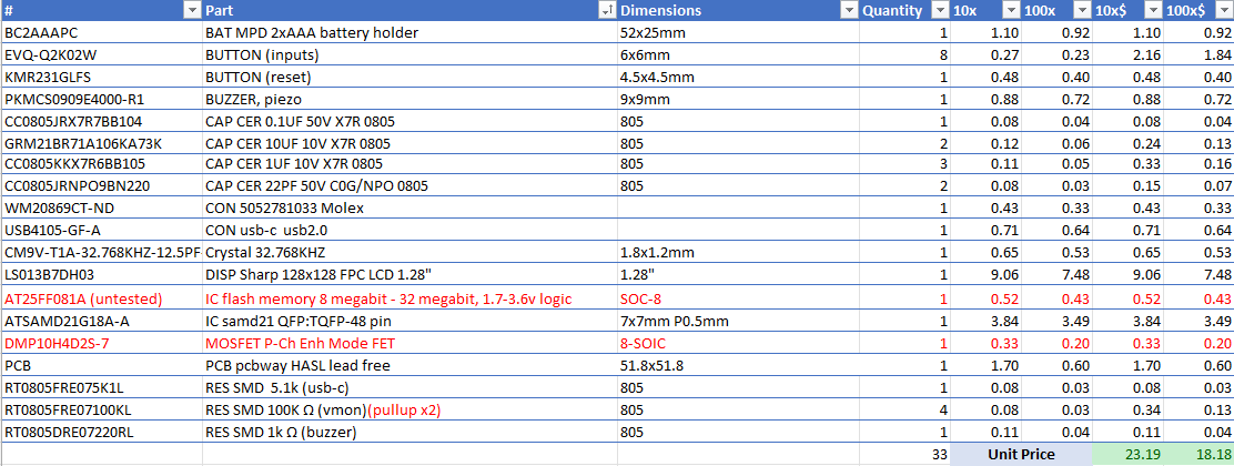
    Current BOM: (red indicates changes from previous design)

  • Waiting on PCBs, New Case!

    NanoCodeBug12/13/2021 at 23:07 0 comments

    While waiting for new PCBs I've been working on an updated case design. The previous case was two solid halves screwed together via 3 x m2.5 screws and heat set inserts. The two halves are still attached this way, but now there is a slide to remove friction fit battery cover. The fit needs to be tight enough on the retaining rails to not accidentally come loose, I'm thinking that a slot for a coin to use as leverage to push open the battery cover might be ideal. 

View all 8 project logs

Enjoy this project?

Share

Discussions

jill5887 wrote 01/10/2024 at 18:47 point

Are you selling these or willing to make a custom one for someone with pay?

  Are you sure? yes | no

Robin LoBuglio wrote 07/11/2023 at 01:57 point

I love these! I would 100% buy a dev kit if you ever got to selling these

  Are you sure? yes | no

Arya wrote 12/12/2021 at 18:36 point

This is adorable ^__^

  Are you sure? yes | no

Similar Projects

Does this project spark your interest?

Become a member to follow this project and never miss any updates