 Vedran
The circuit kinda works, but it leaves a lot to be desired. There's 3 areas that I'd like to improve:
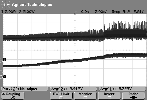
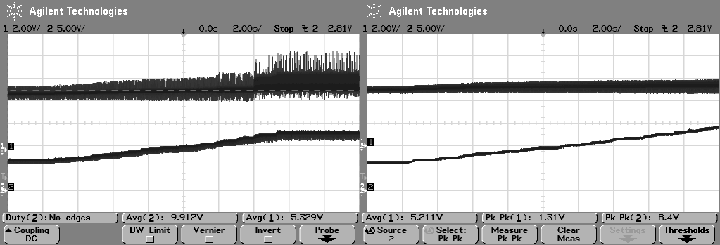
- Input - catches a lot of switching noise going from around ##V (nothing connected) to over 3Vpp once buck converter goes berzerk, around 11V input
- Output ripple - it’s too unstable to be called buck converter. There’s 2.5V of ripple present on the output measurements
- Output floating with input voltage - currently, output will float for about 0.5V when input voltage changes from 6V to 12V. Ideally, there should be no floating
Capacitances
I think the part where I can improve the most is tweaking input/output capacitances. So I grabbed all of my capacitors and started playing around.
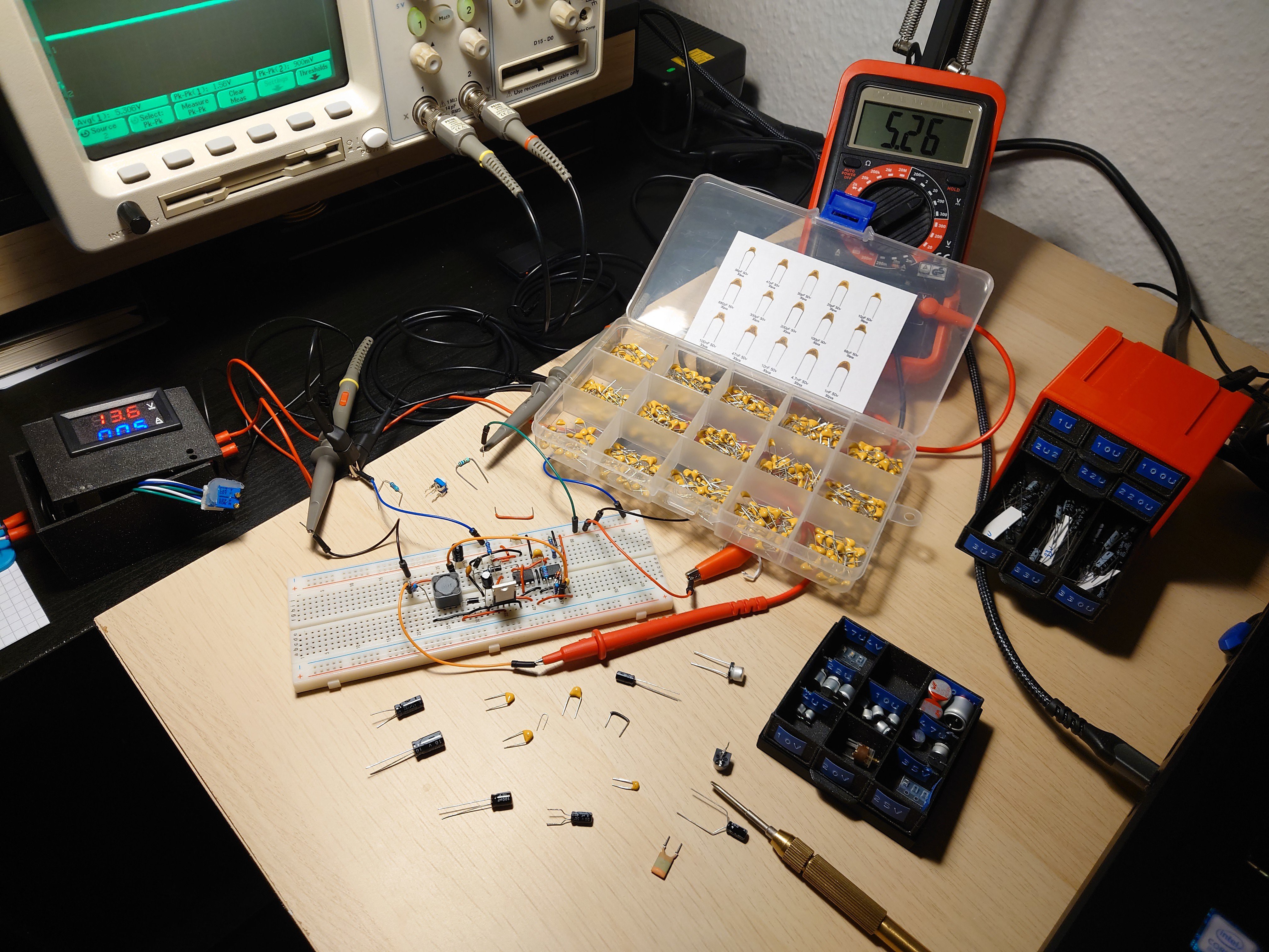
Currently, my physical circuit features only one 10uF input capacitor and one output 33uF capacitor. So I set input voltage to 13V (well in the region where ripple is high) and started testing different capacitors. Trial an error (table below) gave 47u as the best available option.
| Input ripple (VinPP) | Output ripple (VoutPP) | Input capacitance (Cin) |
| 3.4V | 1.4V | 10u |
| 1.5V | 0.9V | 22u |
| 1.7V | 0.9V | 33u |
| 1.4V | 0.9V | 47u |
| 1.8V | 0.9V | 100u |
Or graphically
Discussions
Become a Hackaday.io Member
Create an account to leave a comment. Already have an account? Log In.