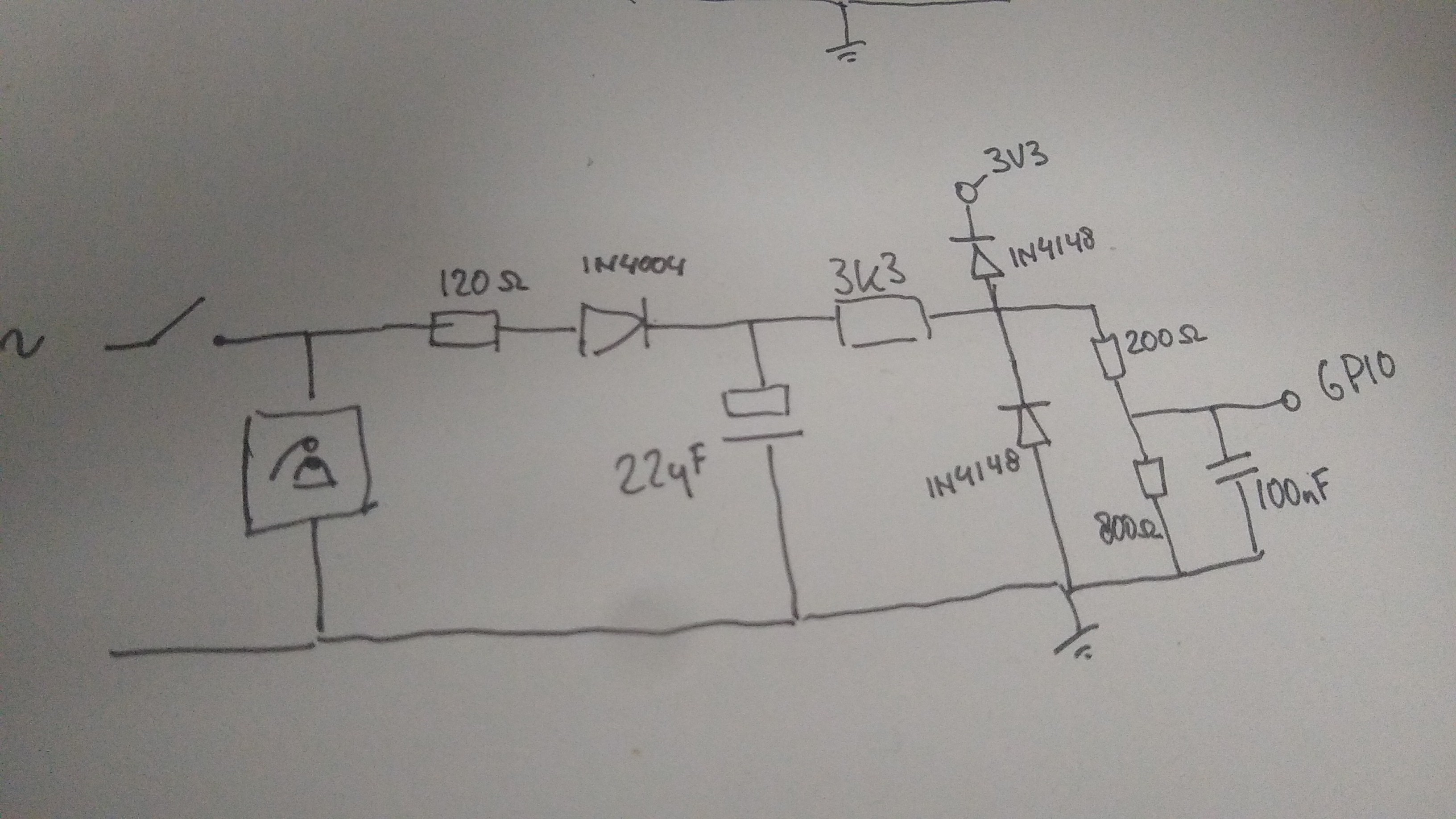
Ok. So the raspberry Pi GPIO's can only handle 3.3V max. I found some solutions that use a full rectifier and then pass the result through a linear voltage regulator. I bet this works, but it feels wrong somehow.
I chose to go with only a single diode and a capacitor to rectify and dampen the signal.
Some clamping diodes to VDD and GND will make sure I'm within GND - 0,7V and VDD + 0,7V. (I don't have any schottky's laying around). And a last voltage divider with two resistors to really make sure I don't go above VDD.
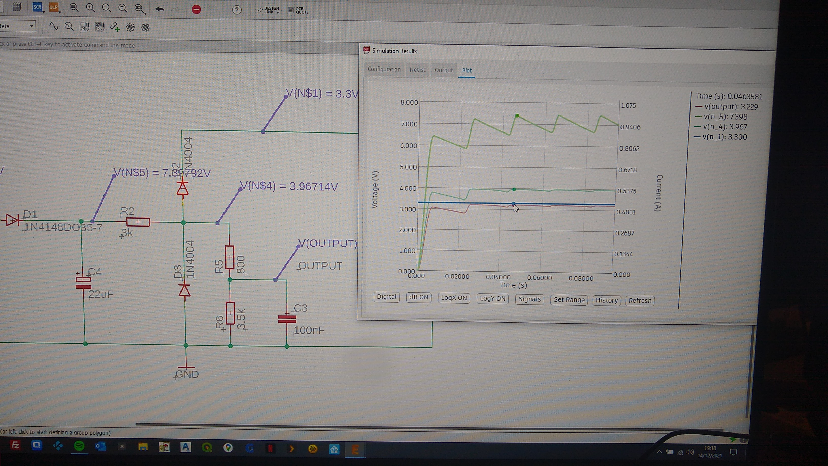
This gave me the chance to (re)learn how to do schematics and simulation. So (quite) a few evenings later:
Then I noticed the relays I had are double latching single coil (I had to google this too). It means they get stuck in ON or OFF position and need a reverse voltage to switch where they also get stuck.
This turns out to be exactly what I want for the mute function that runs in series with the bell-actuator. It just means I have to learn how to do a proper H-bridge. The relays also switch on 5V and the Pi's GPIO-pins give me 3.3V. This means PNP's (I never liked PNP's, they seem upside down somehow and give me headaches)
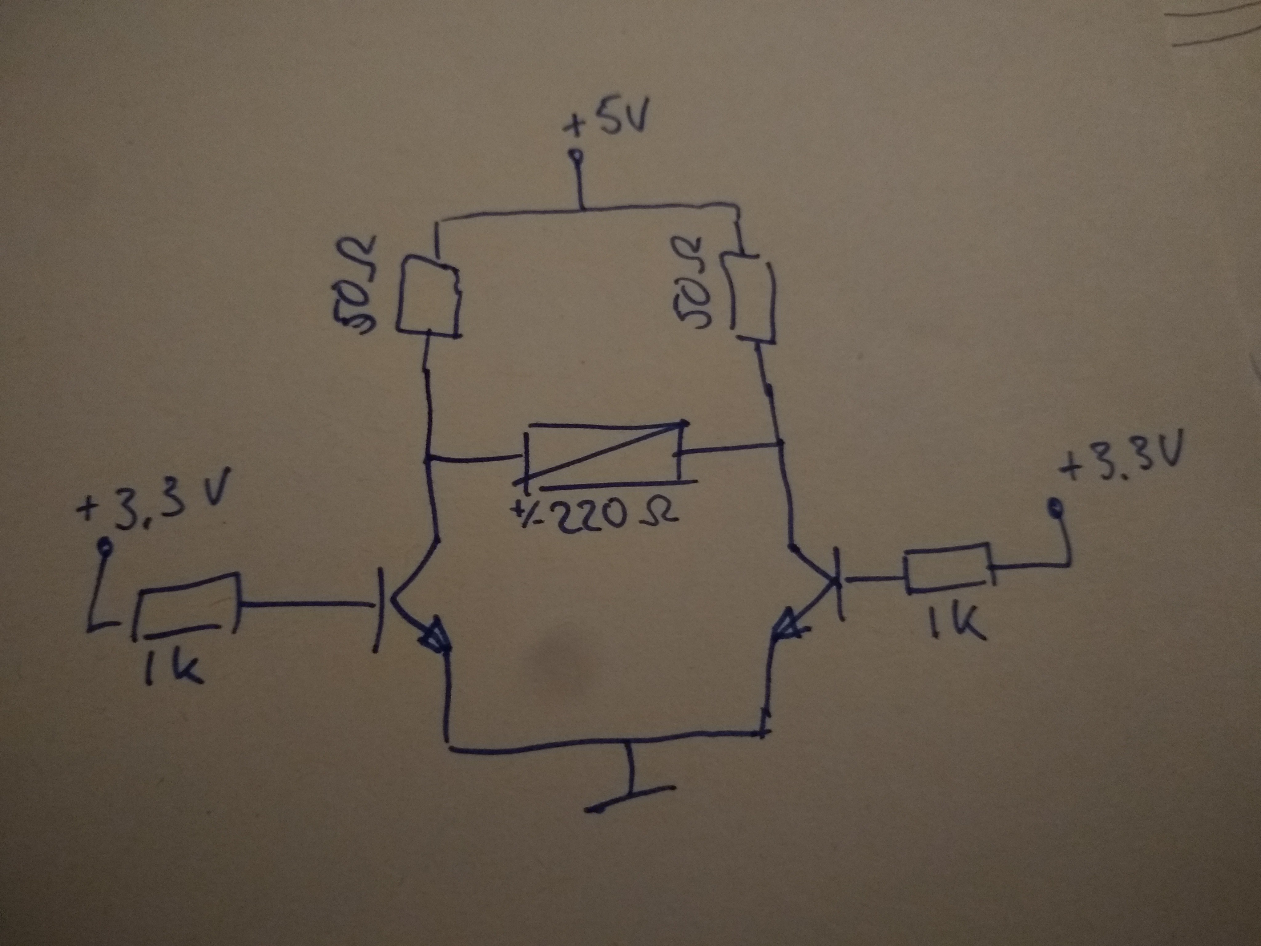
So another full day of research, and an eventual help-line to someone who knows what they are talking about:
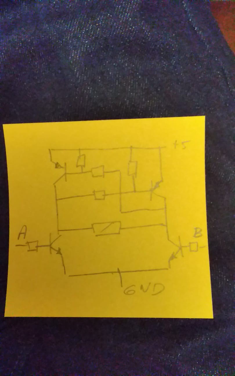
And the full schematic:
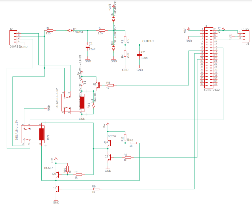
I ended up using one double latching single coil relay for the mute function. The relay has two "sides". One inverted to the other. This gives me an input for the actual status, so I can check this on start-up and check if setting or resetting has worked.
The other relays is parallel to the doorbell button to ring it. It is a "normal" active to close 5V relay that I can operate with a transistor or a button on the board.
This all means the following functionality: I can ring the doorbell with a button on the board or with a GPIO-pin output. This is handy for testing and making my neighbours think I have loads of visitors.
I can mute my doorbell and still get a signal when the doorbell button is pressed (or when I operate the ring-relay. Using the on board button OR a GPIO-pin output).
I also added connections for a DHT22 temperature and humidity sensor. Because, why not?
Discussions
Become a Hackaday.io Member
Create an account to leave a comment. Already have an account? Log In.