Close
0%
0%

Ink and paper MCU programmer

Solving the egg and chicken problem with paper, leds and phototransistors

Similar projects worth following
Final goal is to make a pic programmer that will generate the bitstream using only cheap component found at local electronic store and without using another pic programmer.

Intermediate steps will probably generate bitstream for shorter protocols, such as the APA102 protocol (RGB leds !)

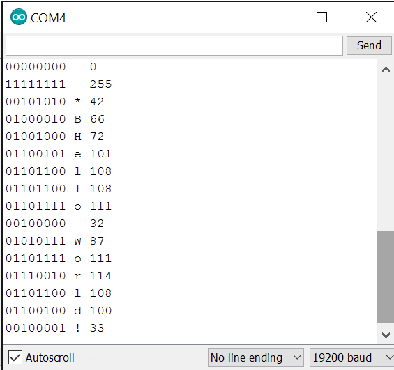
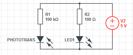
The theory for this project is very simple : have two phototransitors read a strip of paper, generating 0s and 1s to bitbang a data and clock signal to do anything you need.

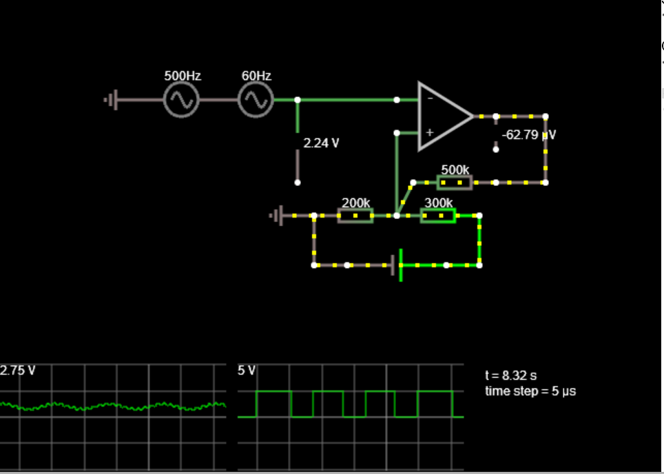
The ouput signal from the phototransistor will be cleaned and amplified to proper levels using an OpAmp. I did'nt knew much about analog electronic when I started this project, but using the OpAmp was easyer than expected.

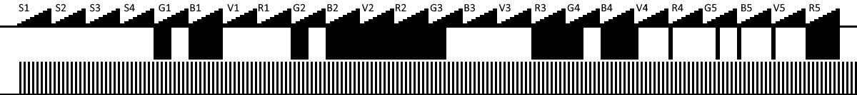
The tricky part might be to get a proper construction : if you manage to read 0.5mm wide band, and can have less than 0.5mm synchronization error between the reading of the data and clock tracks, you will have one bit per millimeter, which means you can only print 32 bytes on a A4 sheet.

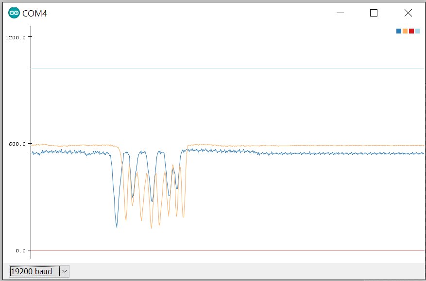
Another problem might be to get something sensitive enough so we don't have to amplify the signal too much (because then we would also amplify any error and noise, leading to potential problems). For now, I use two layers of transparent paper (hence doubling the quantity of black ink), but is would be better to have a single layer of standard paper.

Let's try.

  • 2 × Phototransistor Cheapest one from aliexpress, mine have flat head
  • 2 × Led Fiber Optics / EmittersOld stock blue leds
  • 10 × Resistors You'll need a some stock, or potentiometers to fidn the proper values
  • 2 × OpAmps I use a TLC2272 because I hade it in stock
  • 1 × Breadboard Electronic Components / Misc. Electronic Components

View all 11 components

  • First real usage !

    ftregan11/27/2016 at 10:15 1 comment

    Nope, not programming an µC yet, I started with the simpler APA102 protocol, and here is the result :

    I currently test with 24.5 bytes per A4 sheet (4 start bytes, 5x4 byte for 5 leds, 4 bits stop)

    Here is the strip I used :

    Black means 1, white means 0, this way you read 0s when no strip is inserted. The signal is fed into the negative entry of the opamp, then the opamp will output 1 when light is blocked

    As you may have noticed, the G5 (global luminosity for led 5 which also is a start byt for the led5 frame) is wrong and should start with 3 "1"s instead of 3 "0"s. Once this has been corrected, everything worked fine :)

  • First reason to celebrate !

    ftregan11/26/2016 at 16:36 1 comment

    I received some opamps today (TI TLC2272), and a friend of mine whom printer is not as defectiv as mine printed a picture I gave him and.... it works !

    Well, at least I could read the strip. I would need to read the opamp output at faster rate to be sure there is no false 0 or 1 that the mcu would read during transitions, but when pulled with an arduino, the result is clean !!

    (if you ask, 'B', 66 decimal, is 42 in hexa ;) )

  • Making a better mask

    ftregan11/20/2016 at 11:21 0 comments

    I noticed this morning that the 0.5mm white paper that I used for the mask (cut into a business card) was not stopping the light from the leds. I made a new one with two pieces on aluminium foil on adhesive tape, and the result are way better.

    Now I have to find a good printer to make a more opaque barcode, that will certainly help.

  • Comparator with hysteresis

    ftregan11/19/2016 at 17:52 1 comment

    I found a documentationfrom TI about comparators with hysteresis. (http://www.ti.com/lit/ug/tidu020a/tidu020a.pdf). This combines a schmitt trigger (clean fast and clean transition) with a comparator (output switch does not need to occure at 5V/2, I can center it on the mean ouput of my diode.


    I found a simulator on http://www.falstad.com/circuit/index.html and made a test :
    The first AC voltage is noise (500Hz -+250mV), the second one is signal (2V DC +- 60 Hz 500mV)

    The AOP is set with asymetrical power supply (U- = 0V, U+ = 5V), the 200 and 300 ohm resistor generate the voltage at which the AOP will switch its output (5V * 200 / (200+300) = 2V), then some positiv feedback add hysteresis for a clean signal. Since the feedback is 0 to 5V and not -5V to +5V, this creates an asymetry and the low state is shorter than the high state. This can be compensated by lowering the 200kR, but I'm not sure it will cause trouble in my case. My signal seems to have few noise, I can also raise the feedback resistor to 1MOhm to reduce the effect.

    Since the MCU will have a very high input impedance, it might be needed to add a resistor from the AOP output to the ground, as shown at the end of the page here : https://www.maximintegrated.com/en/app-notes/index.mvp/id/3616

    I need to by an oscilloscope :)

  • Laser ?

    ftregan11/19/2016 at 12:49 0 comments

    Random thought : if I replace the LED with a small cheap laser, I could get a higher light density (hence rising le the tension higher). On the other hand, that would go against the original idea to make an MCU programmer that you could built with part you may already have or could buy for cheap at local store.

    Anyway, I ordered 10 laser pointer (for $0.16 each) on ebay. I'll try using them if I can't get the programmer to work with LEDs.

  • First analyse of the ouput signal

    ftregan11/19/2016 at 12:23 0 comments

    I made a quick setup with two phototransistors, two leds, some resistor, some piece of wood to align everything, some black strips printed on transparent paper, and a 0.5mm wide opening in some heavy paper as a mask. I tryed to tweak everything to get the best result I could, and made some mesurement (using an arduino because my oscilloscop is dead :( ). Here is the result :

    I currently have two problems to solve :

    -The levels are bad (when the resistor after the phototransistor is too low and the signal only raises to about 2.75V, it already too high and the signal only goes down to maybe 1.7V in some cases.

    -The alignement of the two bit streams (data and clock) is poor : first clock (orange) starts about 1 period after the data signal, when it should be half a period.

    Hald a period is 0.25mm, which is an acceptable precision for something that has been hand build, yet is not precise enough. On solution which would solve those two problems at once would be to widen the bands. But imagine you want to flash a 100 byte bootloader, that's 800 bits, and with the protocol overhead, you'll probably need to send about 1200 bits. With 0.5 bands, the paper strip will already need to be 1.2 meters long. I'll try to solutions that does not imply to double this length.

    One thing is sure for now : I have two problems to solve, and I need to separate them and solve them individually so I can manage the complexity.

  • Reading a photo transistor with a voltmeter

    ftregan11/19/2016 at 11:46 0 comments

    I ordered some phototransistors, lots them, ordered again, and made this simple circuit :

    If you read voltage between the phototransistor and resistor when the led cast light to the phototransistor, it read a low voltage (about 0.5V), when there is no light, it read almost 5V. Easy.

  • The idea

    ftregan11/19/2016 at 11:36 0 comments

    You may remember in the old days, when computers hade RS232 serial ports you could use to make a very cheap pic programmer with just a few resistors and diodes, maybe a capacitor. You could then flash an MCU to make a more usable programmer and the chicken and egg problem was solved.

    Nowadays, computers no longer comes with serial ports. Of course you can buy a really cheap usb->serial converter, but they are not really great for bitbanging (because the delay between each usb package is rather long, and for bitbanging you want to send lot and lot of small packet).

    I was thinking about the best way to bitbang a protocol without a microcontroler, and start thinking of perforated cards, barcodes... and thought it might be possible to read a protocol printed on paper with phototransistors.

    I hade to try.

View all 8 project logs

Enjoy this project?

Share

Discussions

Yann Guidon / YGDES wrote 11/19/2016 at 13:33 point

I'll be watching from the back of the room, maybe i'll find interesting tricks to progress with #Low-resolution scanner for cheap data input :-)

  Are you sure? yes | no

ftregan wrote 11/19/2016 at 14:37 point

Certainly some tricks I could get. I was hoping to avoid using an operational amplificator, but since I will need at least a schmitt trigger, maybe I should throw in a quad opamp IC, use two for hysteresis and two to adjust levels and gain (I have not played with opamps since first year in university, if you have any hint for me, I'll take !)

merci,
Fabien.

  Are you sure? yes | no

Yann Guidon / YGDES wrote 11/19/2016 at 14:42 point

I'm sure you can merge the sensitivity and the hysteresis in one OpAmp :-)

Too lazy today to draw anything but I'm sure the Gods here can help us.

  Are you sure? yes | no

ftregan wrote 11/19/2016 at 11:53 point

"You don't think that the bitrate of this paper-reader would be some
orders of magnitude slower than can be achieved by bitbanging the ports
on a FDDI chip?" <- not only do I think, but I know (I won't try to read narrowed than half a milimeter bands, need to bands to generate a clock signals, so I will have one bit every millimeter. I won't try to make the band travel at more than 200mm/s, so 200bit/s is my most optimistic target. 50 is probably more realistic.

Nevertheless, this is how I got the idea : $1 serial to usb adapters did not work well as a pic programmer, so I started thinking about something else.

  Are you sure? yes | no

matseng wrote 11/19/2016 at 12:51 point

I was thinking - how the heck will you be able to read 0.5 mm bands? The sensitive area on a ldr or photodiode/transistor is much wider that that.

Then I saw the post about using a slot to block off the area outside of the 0.5mm band.

I must be really slow to not instantly figure out that myself. ;-)

  Are you sure? yes | no

ftregan wrote 11/19/2016 at 13:00 point

Actually, I was surpised but the sensitive part of the photostransistor is very narrow, less than a milimeter. It might be possible that, using a focused laser instead of an LED, you don't even need a mask.
Unfortunately, I don't know where my lasers are, so I ordered ten.  Maybe I'll have them for christmas.

  Are you sure? yes | no

matseng wrote 11/19/2016 at 11:44 point

Cool idea. Looking forward to see some progress!  

But I LOL'ed at this "...are not really great for bitbanging (because the delay between each usb package is rather long..."

You don't think that the bitrate of this paper-reader would be some orders of magnitude slower than can be achieved by bitbanging the ports on a FDDI chip?


  Are you sure? yes | no

Similar Projects

Does this project spark your interest?

Become a member to follow this project and never miss any updates