 Sam Ettinger
So, what resources do we have that would let us figure out the workings of these LED panels? It's clear that there's more going on than just LEDs and batteries, but what, exactly?
In August I learned that there are pretty hi-res photos of the boards! There are some very helpful ones from Flickr user vanderlin, used here under the CC-NC-SA license. I found another source of photos later, which I'll get to in a bit.
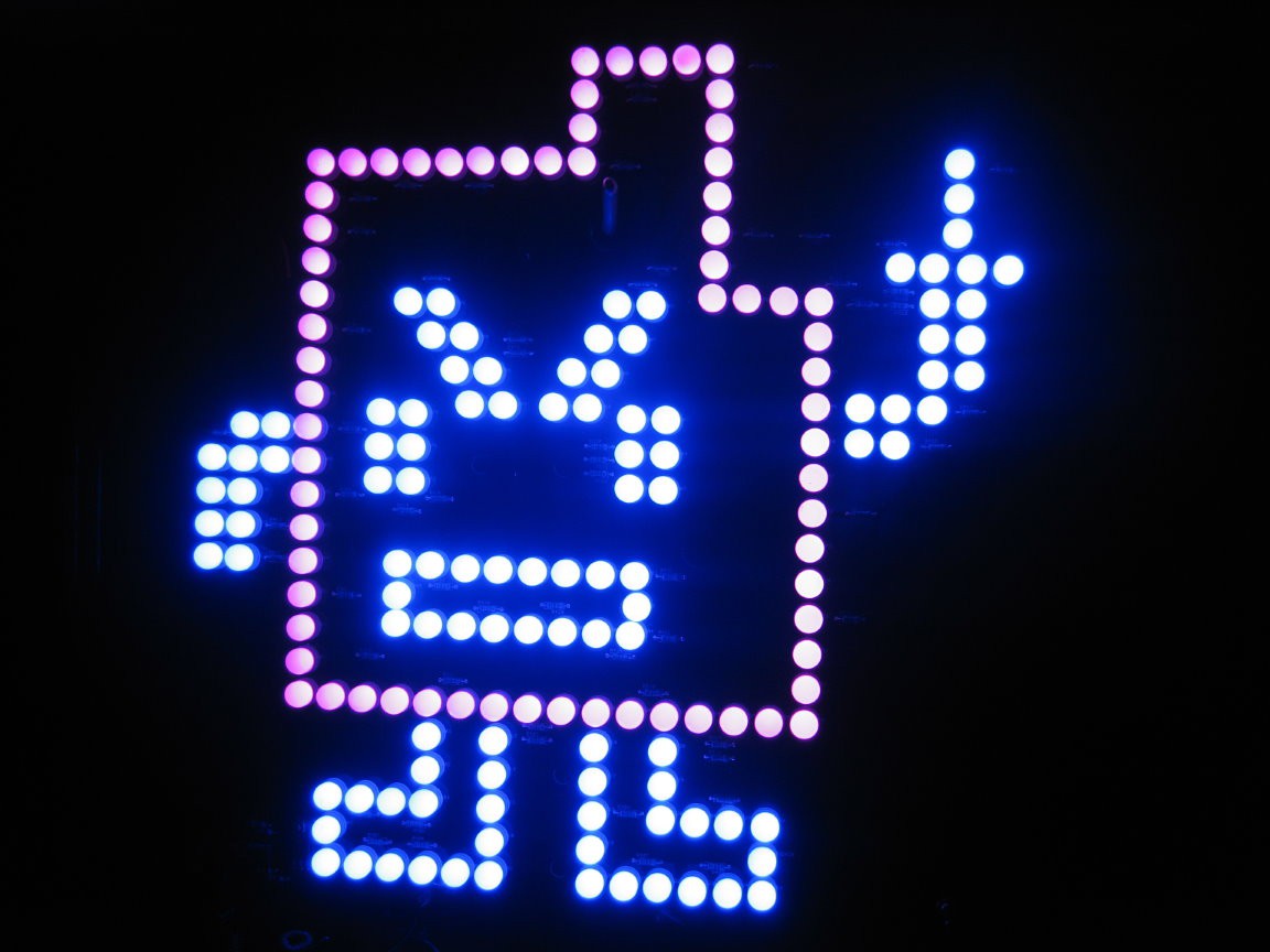
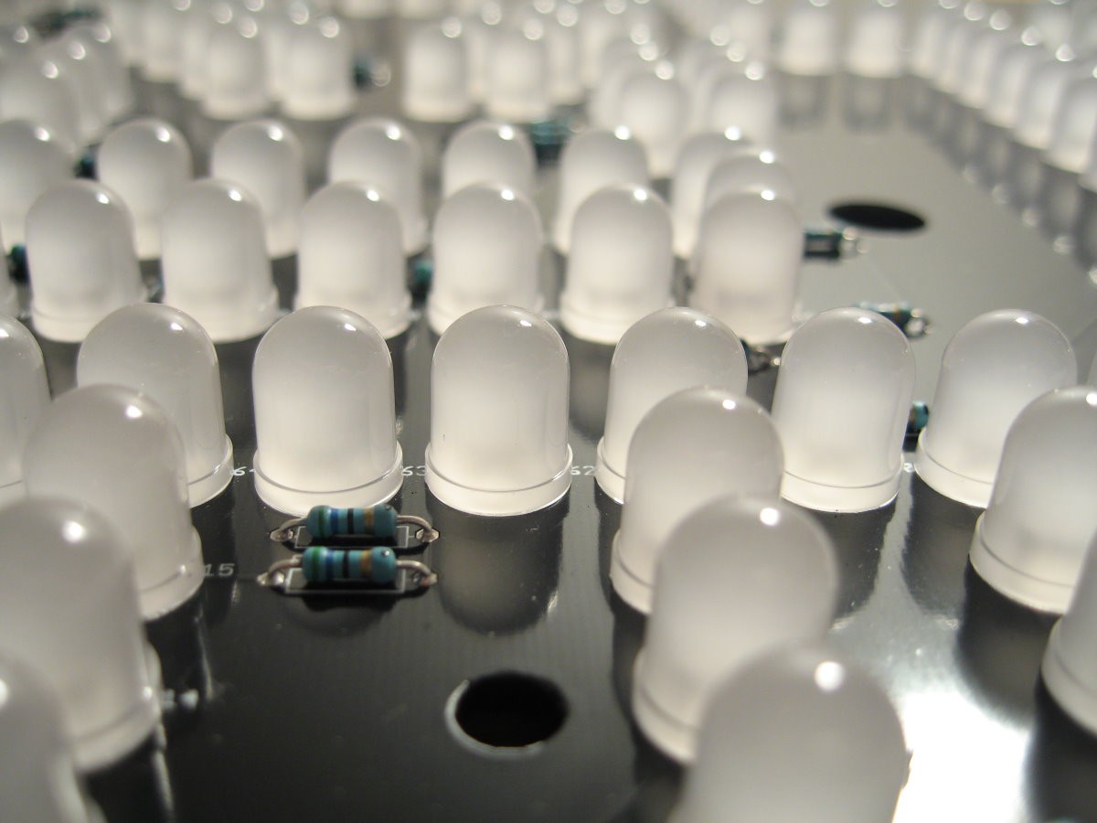
There are 177 10mm through-hole LEDs. 68 violet, 109 blue, plus 59 scattered resistors. So the LEDs are definitely arranged with one current-limiting resistor for three LEDs. Blue and violet LEDs have 3.3V-ish forward voltages, and the resistors look like they are 56Ω. I think they are being powered with a 12V supply, which would mean about 36 mA current through the LEDs at peak consumption. And I think they are only rated for 20 mA, so...maybe Boston PD was correct that it was dangerous? (Sarcasm)
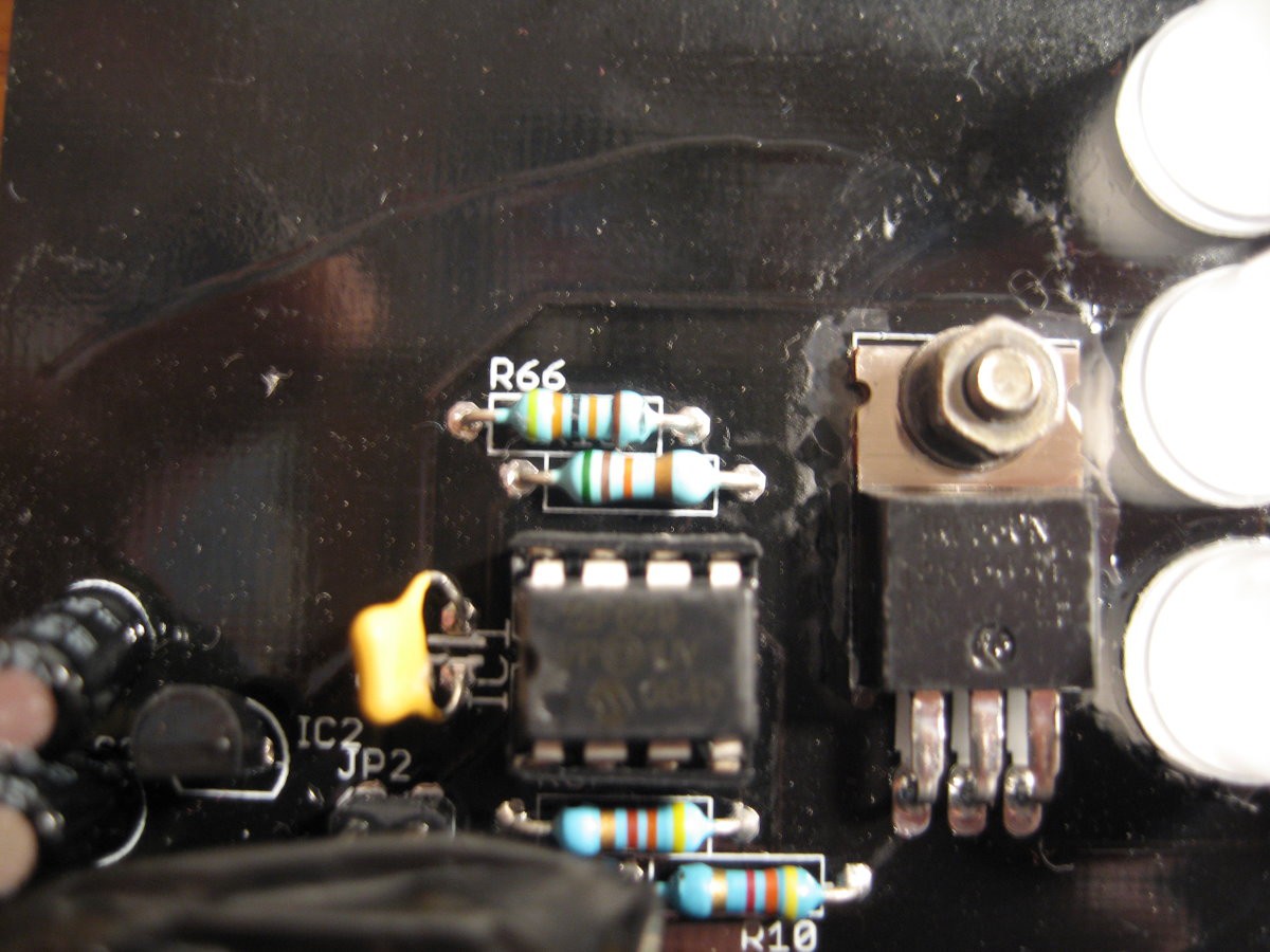
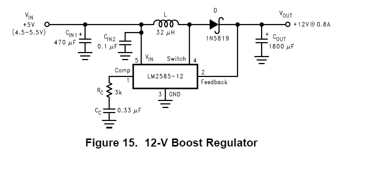
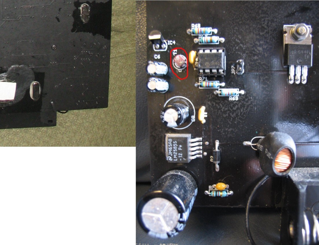
We can see in the Flickr photos a PIC12F629 microcontroller and a TO-220 that vanderlin annotated as a "5V regulator," but it's more likely to be a MOSFET. There are also some oblique shots of another IC that was lurking under some duct tape. I spent a loooong time trying to figure out what it was based on just the Flickr photos. The package looks like a TO-263-5, the second line ends with "SS" or "5S", the third line ends with "P+", and it is surrounded by a boost-converter-looking circuit. I was able to suss out from just this that it's a National Semiconductor (now Texas Instruments) LM2585S, and was feeling pretty good about that!
Then I discovered that, in the description of a Wikimedia photo, there is a (broken) link to a JPEG on a Georgia Tech student page, and if you go to the parent directory of that photo on archive.org, there is a trove of more photos! These ones make it clear that, yes, it's the LM2585S, but it was still fun to do the detective work, at least.
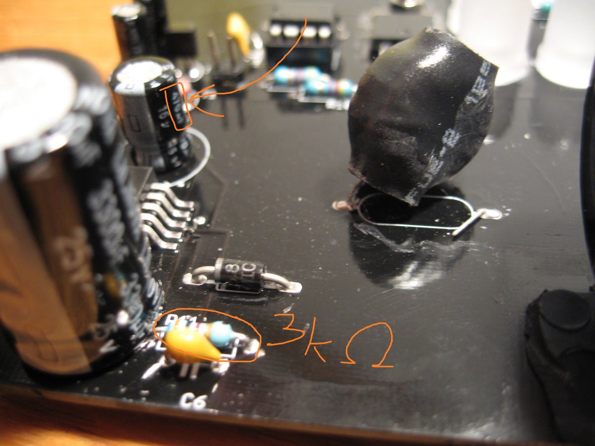
As for the circuit around the LM2585S, there's a 3 kΩ resistor visible, a 470μF and a 0.1μF cap, an inductor, a (Schottky) diode, and a fat capacitor. This perfectly matches the example circuit in the IC's datasheet. So that's a big chunk of the circuit solved!
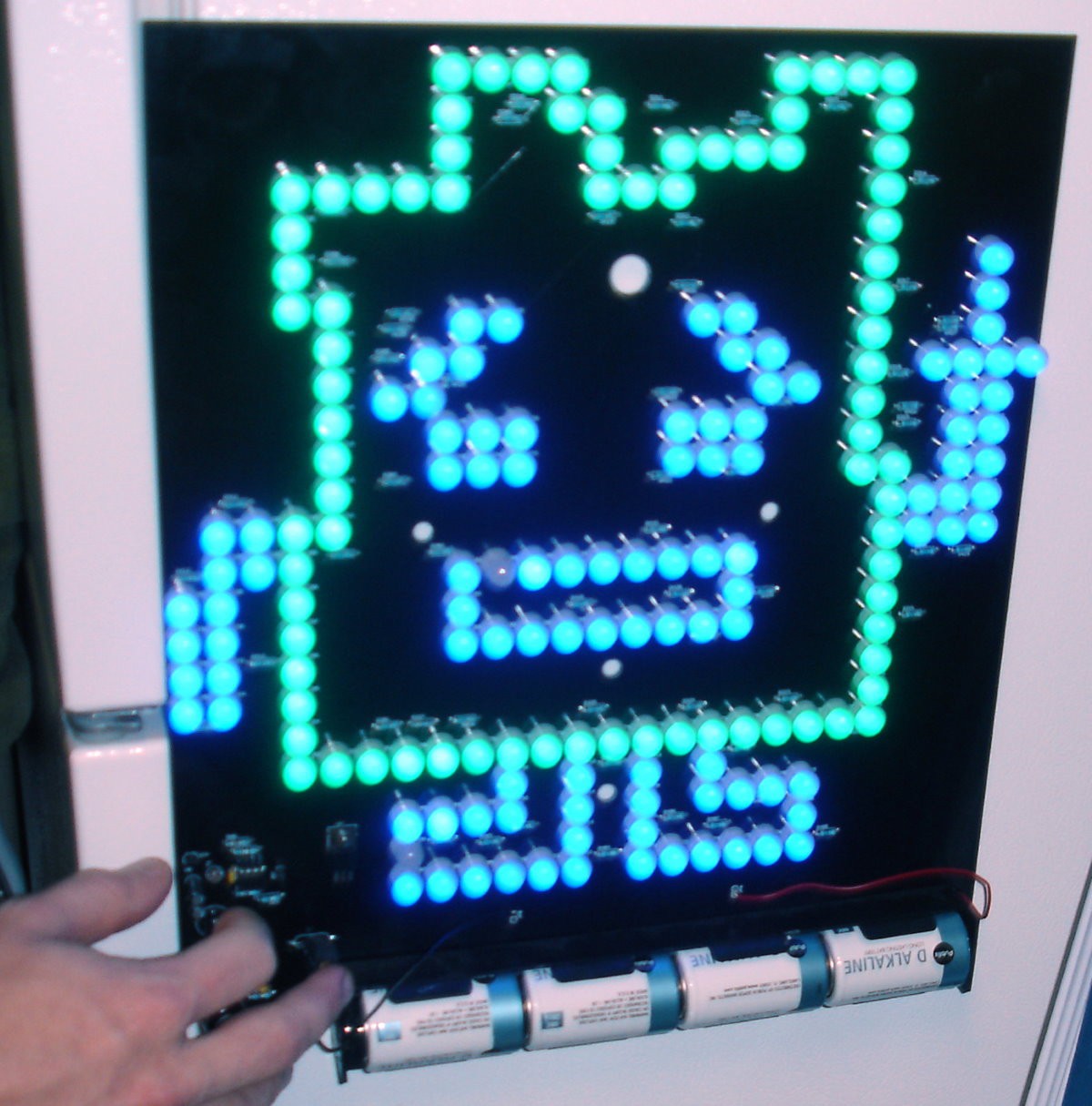
The Georgia Tech photos depict a different Mooninite, namely, Ignignokt (the other one is Err). Ignignokt is made up of 100 blue and 80 green LEDs with 60 current-limiting resistors (also 56Ω).
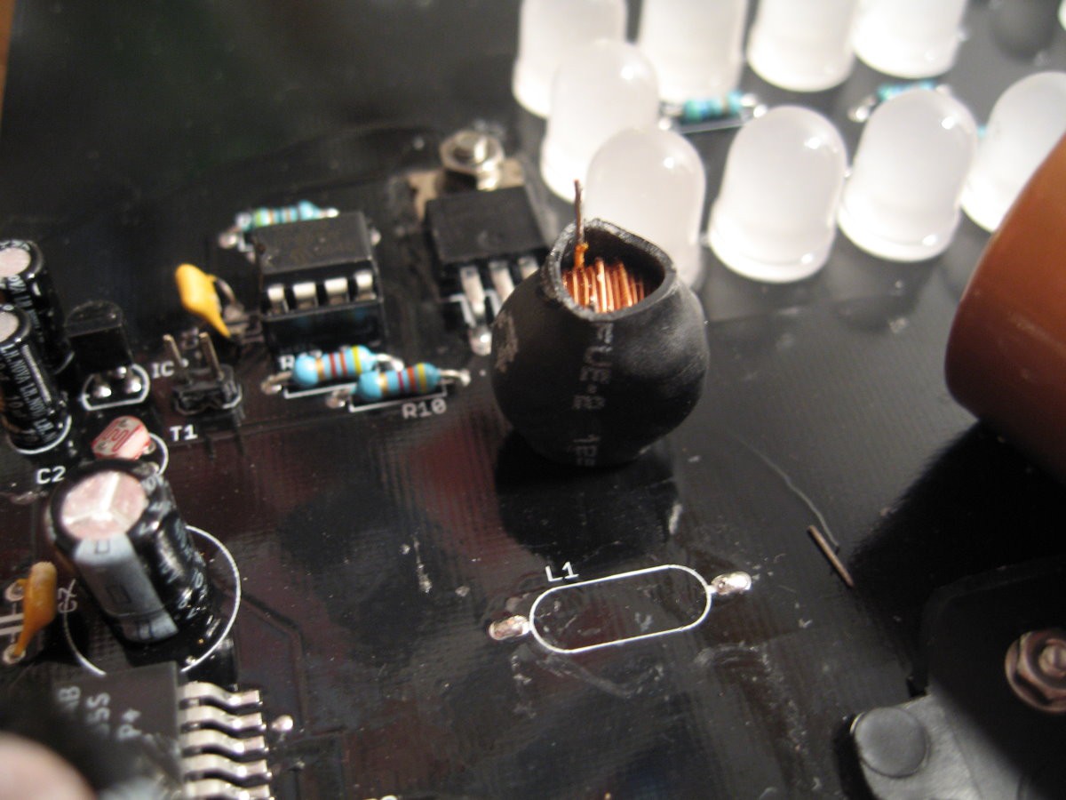
Remaining mysteries on the board: there's a 51kΩ and a 430kΩ resistor above the PIC, and two 4.3kΩ resistors below it. There's a photoresistor, a 10μF cap, a 1μF cap, a mysterious TO-92 package and a mysterious TO-220 package. Oh, and a jumper.
I haven't seen video of this happening, but it seems like the board adjusts its brightness depending on the light sensor reading. It looks like there are multiple brightness levels, not just ON/OFF, but I haven't seen video to really confirm. So the PIC12F62 is taking an analog voltage reading from the photoresistor to detect brightness, right? Wrong! PIC12F62 can't read analog inputs! And that's where one (or both?) of the capacitors comes in.
When you don't have an analog-to-digital converter handy, you can instead measure how long it takes a capacitor to charge/discharge. Here's a really nice summary from Adafruit.

I'm really not sure why there are two capacitors, though. Maybe it's to get useful measurements over a wider range of brightnesses? But if that were the case, I would assume they would be, like, 1μF and 470μF, not 1μF and 10μF. I really don't know. (I will posit a theory further down, though)
Finally, we get to the TO-220 and the TO-92. Like I said, the Flickr album calls the TO-220 a 5V regulator, and I disagree. The board has to control something like 6 Amperes' worth of LEDs! There has to be a power MOSFET somewhere, and this is the only place that makes sense.
Between the Atlanta photos and the Boston photos, I can't make out exactly what the TO-220 is, but: it's got the logo of International Rectifier (now part of Infineon), it was made in week 44 of 2006, it's Pb-free, and came from lot 18EH. If you squint you can make out the letters ??RF???N, maybe. International Rectifier makes several TO-220 FETs with the code "IRF___N."
All the TO-220 FETs I saw are GDS: pin 1 = gate, pin 2 = drain, pin 3 = source. It looks like there's
a 4.3kΩ resistor between pin 1 and a PIC pin; pin 2 heads toward the
batteries, probably to ground; and pin 3 goes directly into one the
current-limiting resistors. This makes sense for an N-channel MOSFET.
International Rectifier did also make 5V regulators in TO-220 packages, but if this was one of those, I'd expect to see pin 1 go to ground (not the PIC), pin 2 go to the PIC (not to ground), and Pin 3 to either the batteries or the 12V rail (not the LEDs). It doesn't match at all.
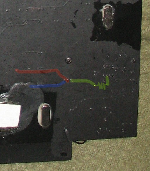
Now, what about the TO-92? I am not as confident in my answer here! If this were an LDO to power the PIC, it would make sense, but that package almost always indicates "generic transistor." But I can't think of a good reason to have a transistor here. On the back of the Atlanta board, I think I see a trace going from
TO-92 pin 1 to PIC pin 4 via R71, and a trace going from TO-92 pin 3
to PIC pin 5 AND the ground pin? But there's so much conformal
coating I can't actually identify anything. This is like finding
canals on Mars. (Ignore the red circle around the photoresistor; that was in the original upload and not added by me)
It could feasibly be a transistor. "Nightlight" circuits like the one below are a common "learn about transistors and photoresistors" thing! When I was little I strung a pair of these from one end of the house to the other, so we could tap out Morse code messages. Ah, memories ❤️
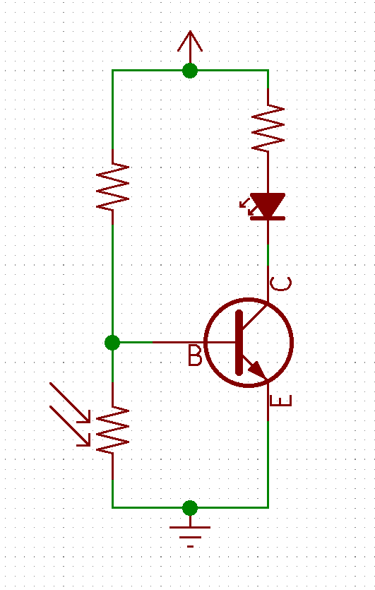
That said, I can't think of a way to adapt that nightlight circuit system for a PIC with no analog input. You could do a digital timing thing like I described above, but if you're going to do that, why bother with the transistor at all?
Also, the reference designator says "IC." If it was a BJT it would probably say "Q." Then again: maybe it depends on the software they used? What was EDA software like in 2006, I have no idea. Didn't PADS always label transistors as "IC", or is that an artificial memory? Whatever. The only thing that makes sense to me is if it's a 5V regulator. Or some other regulator in the 2.0 – 5.5 V range. I'm ready to move on.
That leaves very few parts unexplained. According to my notes, someone online (I forget where) explained that the jumper sets the display to stay lit and ignore the brightness reading. The PIC has internal pull-up resistors on all the I/O ports, so I doubt any of the board resistors are pull-ups or pull-downs.
This seems kind of silly, but maybe there are two capacitors because the PIC is taking TWO analog readings! The first is the ambient brightness, of course, maybe the second is the battery voltage? The 430kΩ and 51kΩ resistors would make sense with that approach, I think. The difference between a full-charge reading and a near-dead-battery reading would be small, only a 10-15 milliseconds difference, but with a 4MHz clock that would be very doable. It seems...outlandish to put a low-battery detector on this, though. I mean, if it detects low battery, what's it going to do? Call Carl Brutananadilewski? Let me know if you can think of some other reasons for these parts.
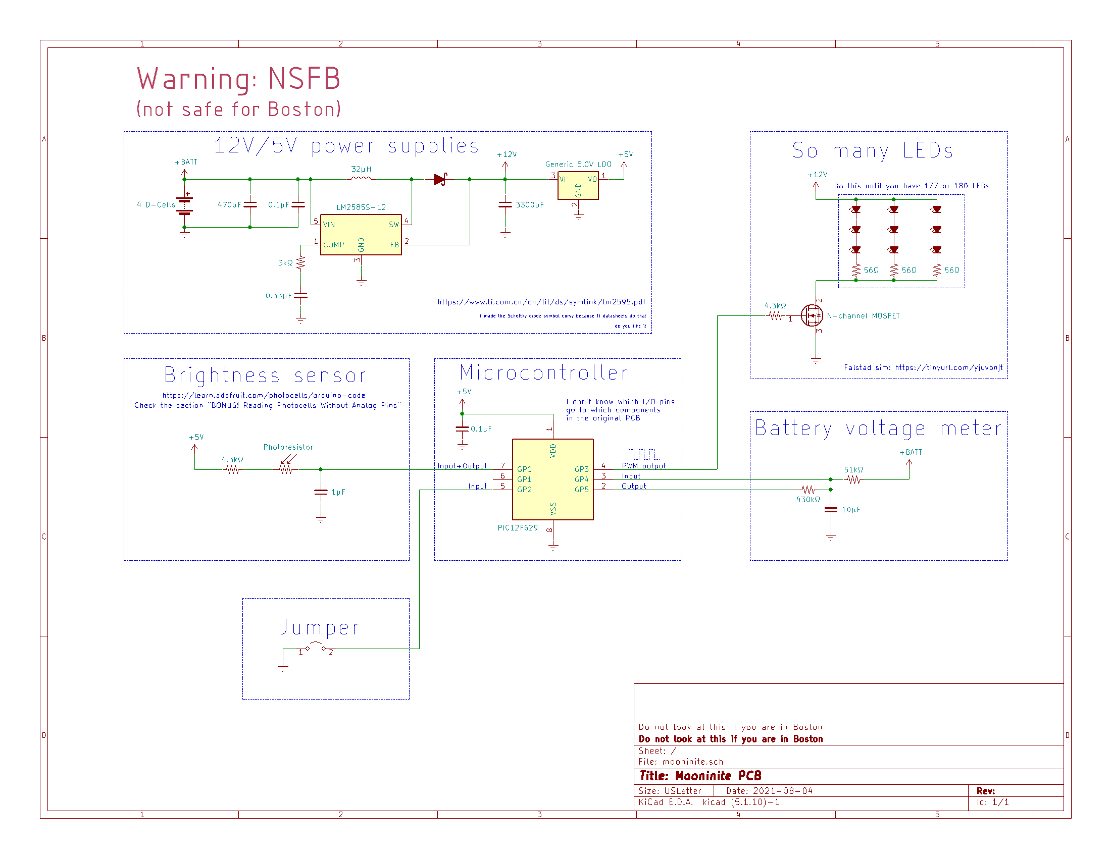
Finally, here is the schematic, reverse-engineered to the best of my ability. I welcome your input. If you have access to one of the original boards, please get in touch!
Finally finally, thanks for exploring this project together. The original incident really struck a chord with me as a teenager. I like to think teenage-me learned some lesson from it, like the power of art and electronics as an art medium. Maybe that's silly.
🖕 THE 🖕 END 🖕