 Sam Ettinger
So, what resources do we have that would let us figure out the workings of these LED panels? It's clear that there's more going on than just LEDs and batteries, but what, exactly?
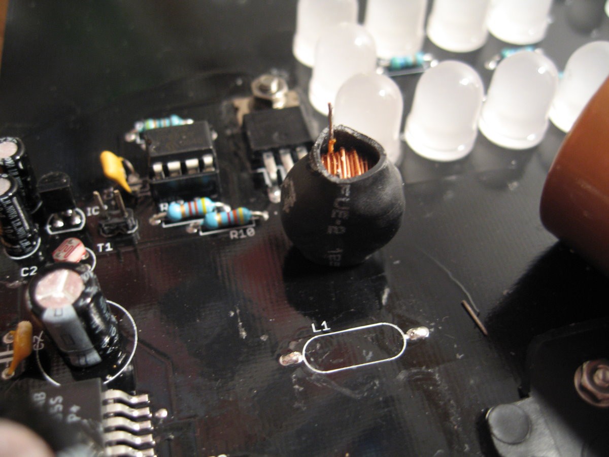
In August I learned that there are pretty hi-res photos of the boards! There are some very helpful ones from Flickr user vanderlin, used here under the CC-NC-SA license. I found another source of photos later, which I'll get to in a bit.
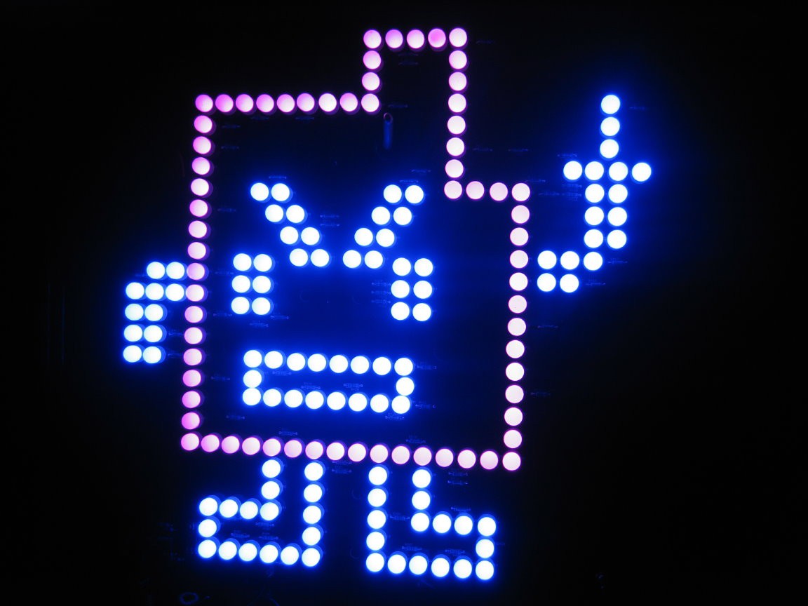
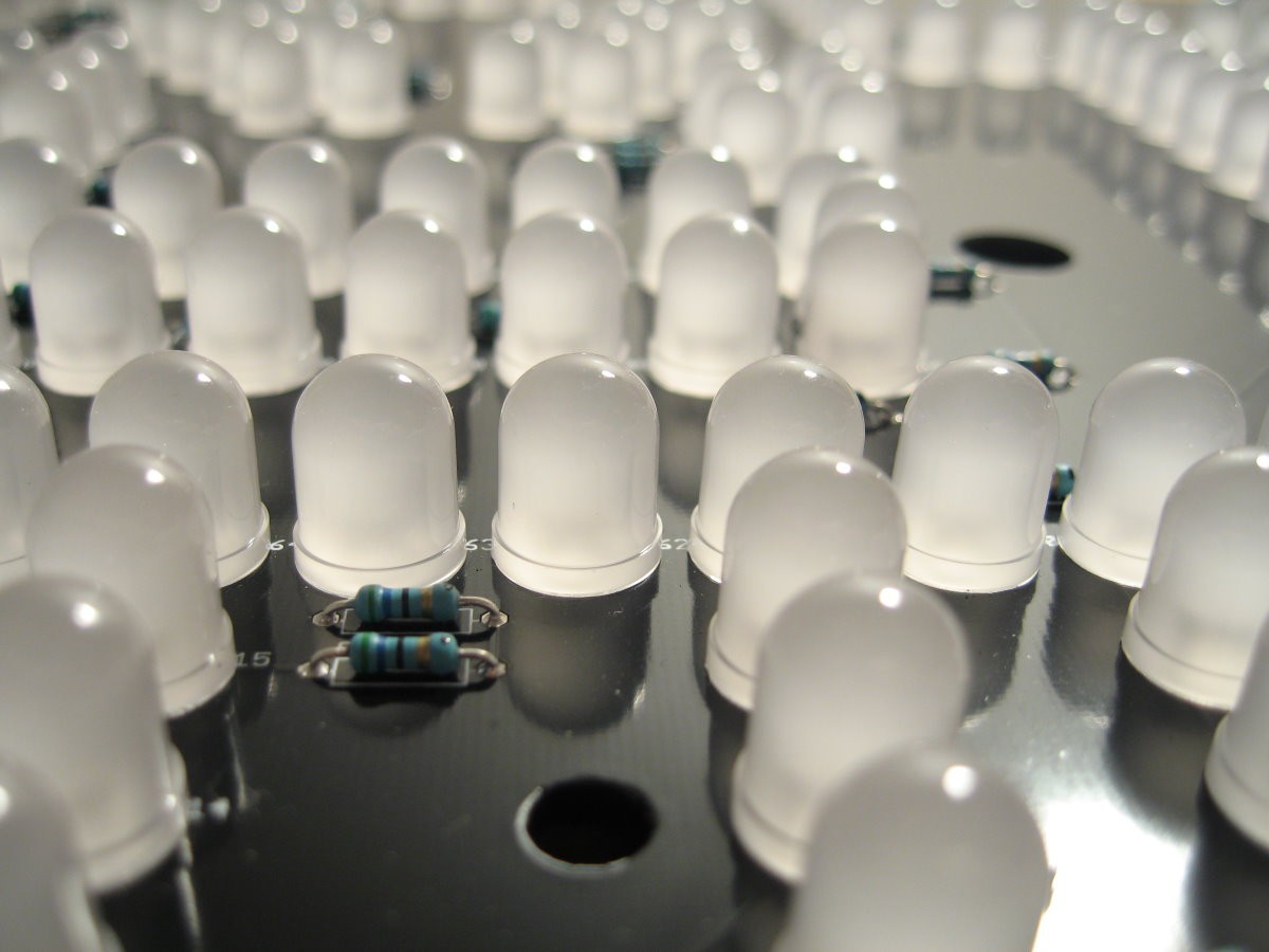
There are 177 10mm through-hole LEDs. 68 violet, 109 blue, plus 59 scattered resistors. So the LEDs are definitely arranged with one current-limiting resistor for three LEDs. Blue and violet LEDs have 3.3V-ish forward voltages, and the resistors look like they are 56Ω. I think they are being powered with a 12V supply, which would mean about 36 mA current through the LEDs at peak consumption. And I think they are only rated for 20 mA, so...maybe Boston PD was correct that it was dangerous? (Sarcasm)
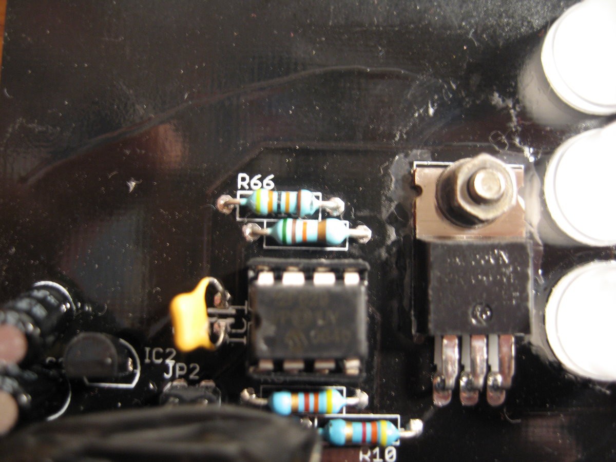
We can see in the Flickr photos a PIC12F629 microcontroller and a TO-220 that vanderlin annotated as a "5V regulator," but it's more likely to be a MOSFET. There are also some oblique shots of another IC that was lurking under some duct tape. I spent a loooong time trying to figure out what it was based on just the Flickr photos. The package looks like a TO-263-5, the second line ends with "SS" or "5S", the third line ends with "P+", and it is surrounded by a boost-converter-looking circuit. I was able to suss out from just this that it's a National Semiconductor (now Texas Instruments) LM2585S, and was feeling pretty good about that!
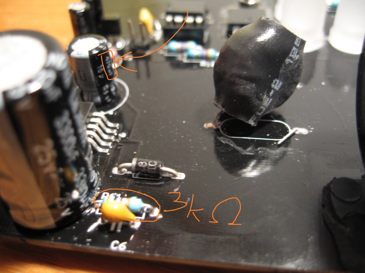
Then I discovered that, in the description of a Wikimedia photo, there is a (broken) link to a JPEG on a Georgia Tech student page, and if you go to the parent directory of that photo on archive.org, there is a trove of more photos! These ones make it clear that, yes, it's the LM2585S, but it was still fun to do the detective work, at least.
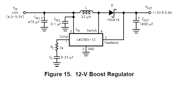
As for the circuit around the LM2585S, there's a 3 kΩ resistor visible, a 470μF and a 0.1μF cap, an inductor, a (Schottky) diode, and a fat capacitor. This perfectly matches the example circuit in the IC's datasheet. So that's a big chunk of the circuit solved!
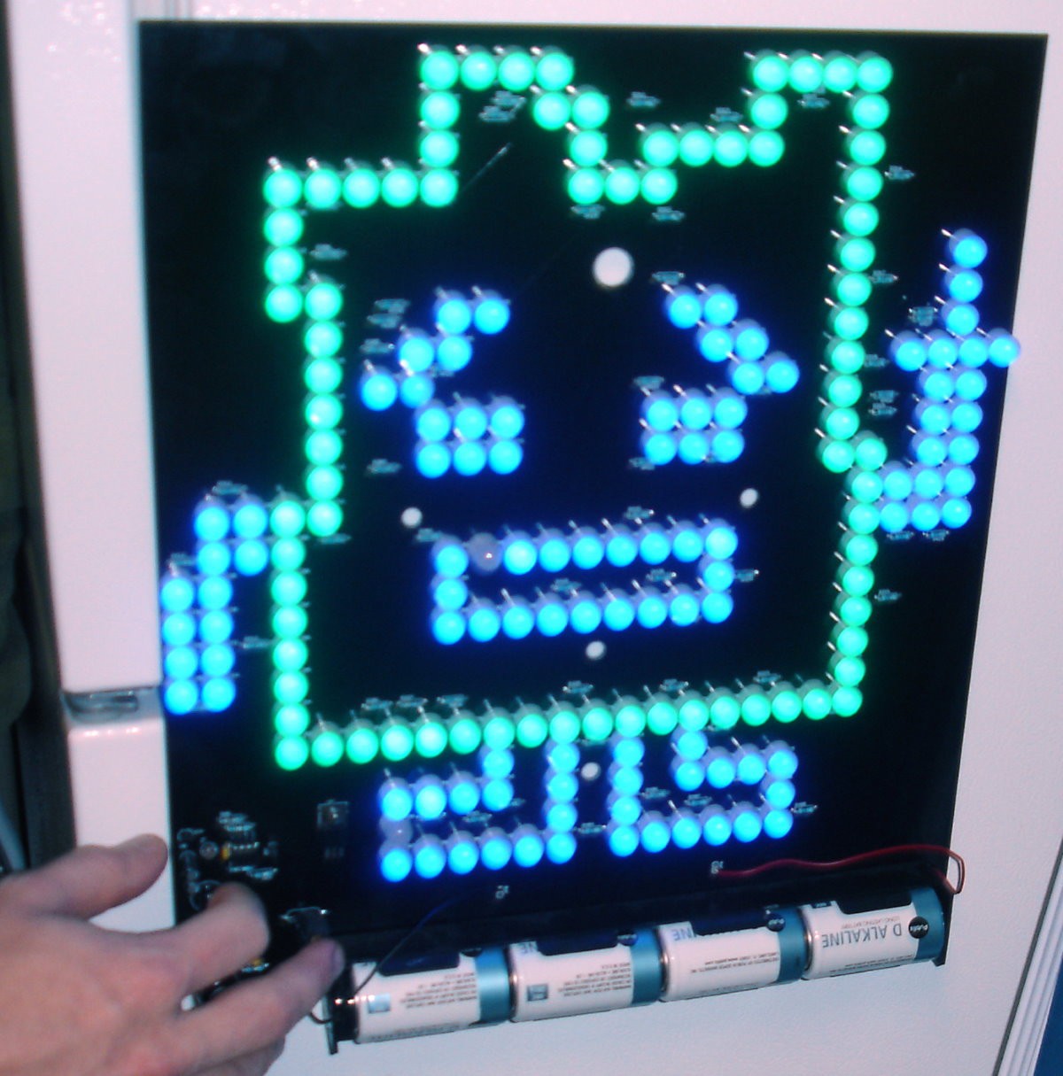
The Georgia Tech photos depict a different Mooninite, namely, Ignignokt (the other one is Err). Ignignokt is made up of 100 blue and 80 green LEDs with 60 current-limiting resistors (also 56Ω).
Remaining mysteries on the board: there's a 51kΩ and a 430kΩ resistor above the PIC, and two 4.3kΩ resistors below it. There's a photoresistor, a 10μF cap, a 1μF cap, a mysterious TO-92 package and a mysterious TO-220 package. Oh, and a jumper.
I haven't seen video of this happening, but it seems like the board adjusts its brightness depending on the light sensor reading. It looks like there are multiple brightness levels, not just ON/OFF, but I haven't seen video to really confirm. So the PIC12F62 is taking an analog voltage reading from the photoresistor to detect brightness, right? Wrong! PIC12F62 can't read analog inputs! And that's where one (or both?) of the capacitors comes in.
When you don't have an analog-to-digital converter handy, you can instead measure how long it takes a capacitor to charge/discharge. Here's a really nice summary from Adafruit.

I'm really not sure why there are two capacitors, though. Maybe it's to get useful measurements over a wider range of brightnesses? But if that were the case, I would assume they would be, like, 1μF and 470μF, not 1μF and 10μF. I really don't know. (I will posit a theory further down, though)
Finally, we get to the TO-220 and the TO-92. Like I said, the Flickr album calls the TO-220 a 5V regulator, and I disagree. The board has to control something like 6 Amperes' worth of LEDs! There has to be a power MOSFET somewhere, and this is the only place that makes sense.
Between the Atlanta photos and the Boston photos, I can't make out exactly...
Read more »

 Kevin Santo Cappuccio
 Hulk
Hulk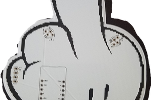
 El Jefe
 Mike
Mike
One other thing. I designed the board around the 3 LEDs/resistor theory but crunching the numbers it could be 4. Looking at Ignignokt specifically (let's focus on the top). There are roughly 9 resistors for 36-ish LEDs. Also, the mouth has 20 LEDs with exactly 5 resistors. The left eye has 12 LEDs with 3 resistors. Right arm is 12 LEDs with 3 resistors. And so on,. I ordered a bunch of diffuse LEDs from China and, despite the specs saying 3.2v, they seem to have a forward voltage drop of about 2.8v measured using two different methods. If we assume they are running these at 15 mW (slightly lower than the max of 20 mW) then 4 LEDs + one 56 ohm resistor would be correct. The only issue is this would have a single LED on one resistor so somewhere the grouping is different given Ignognokt has exactly 185 LEDs.
I will probably create a second Ignignokt variant with 4 LEDs/resistor.