 Bradley Austin Davis
I'd previously thought that to support any kind of camera functionality I'd need at least a Raspberry Pi level board, but I recently discovered the ESP32-CAM boards which support connecting a camera. However, they're less developer friendly than the ESP32 development boards I've been using and don't include a built-in USB connection for programming. So although I received a couple from Amazon yesterday, I couldn't use them until I got an FTDI programmer to bridge that gap. Fortunately that arrived this morning and I've spent the better part of the time since it showed up trying to load up a test program (mostly following these instructions) on it that would stream the camera image over a web-stream.
I encountered three major issues while trying to get this done. The first was a debugging problem. In order to program the board you need to short GPIO 0 to GND. The guide suggested that you should power down the board before removing that connection. However, it looks like the Arduino IDE Serial Monitor doesn't really like the COM port being listened to to vanish and re-appear. I finally figured out I could get it to start listening again by switching the baud to another value and back again (I'm using 115,200 baud normally). So in order to test out any change to the program the steps were
- Disconnect the USB port
- Short GPIO 0 to GND
- Reconnect he USB port
- Tell the Arduino IDE to upload
- Disconnect the USB port
- Remove the short
- Reconnect the USB port
- Toggle the speed on the serial monitor
- Hit the reset button on the board
Which is a far cry from the developer board experience of "Press upload". Regardless once I figured out the process I was able to get debug output, which led me to my second problem.
The linked guide above says
I have found the 3.3-volt set up to be more reliable, which is why I am recommending it.
However, once I started getting debug output, I saw that when I powered the board in this way, I got a looping "Brownout detector was triggered" message from the board. Reading up on the FT232RL board I found some sources that suggested that you could draw up to 500 mA in 5v mode, but only 50 mA in 3.3v mode. So I switched the voltage mode on the programmer and swapped to the 5v input pin on the ESP32-CAM board (as well as wiring the ground to the GND pin right next to the 5v pin) and suddenly the board was booting and trying to connect to Wifi.
Here's where I ran into my third problem: the antenna connection
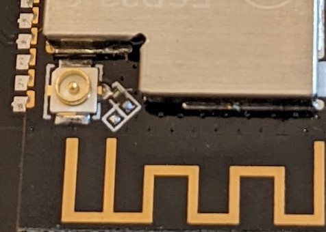
If you look at this image you'll see the built-in antenna running on the bottom of the board, and a pigtail connector on the left side. Finally there's a small boomerang area where a 0 Ohm resistor is put into one of two positions to enable either the internal antenna or the pigtail connector. I have 3 boards and two of them have the internal connector enabled, while the third has the pigtail enabled. In the case of the pigtail connector being enabled, if there's no actual external antenna connected, then while the board can "hear" my main WiFi access point, it can't transmit loud enough to maintain a connection. I figured this out when I saw the connection state cycling between WL_DISCONNECTED and WL_CONNECTION_LOST, and examined the pigtail connector resistor. I just count myself lucky that the guide I was using talked about how to work with an external antenna or I would never have thought to check this.
Once I switched to one of the other boards that was wired to use the built-in antenna, it connected to my network just fine and I was able to see the web server and stream the camera image in a browser. This proof of concept gives me enough to ensure I can use these chips in the feeders and extend the functionality to include monitoring the bowls to ensure they're getting food and not jammed. On the one hand I could also see who's eating what, but now that I think about it, it would probably be easier to do that by having an RFID detector in the mix and adding an RFID chip to each of the pets collars.
Discussions
Become a Hackaday.io Member
Create an account to leave a comment. Already have an account? Log In.