0%
0%
Recycled IoT pet feeders
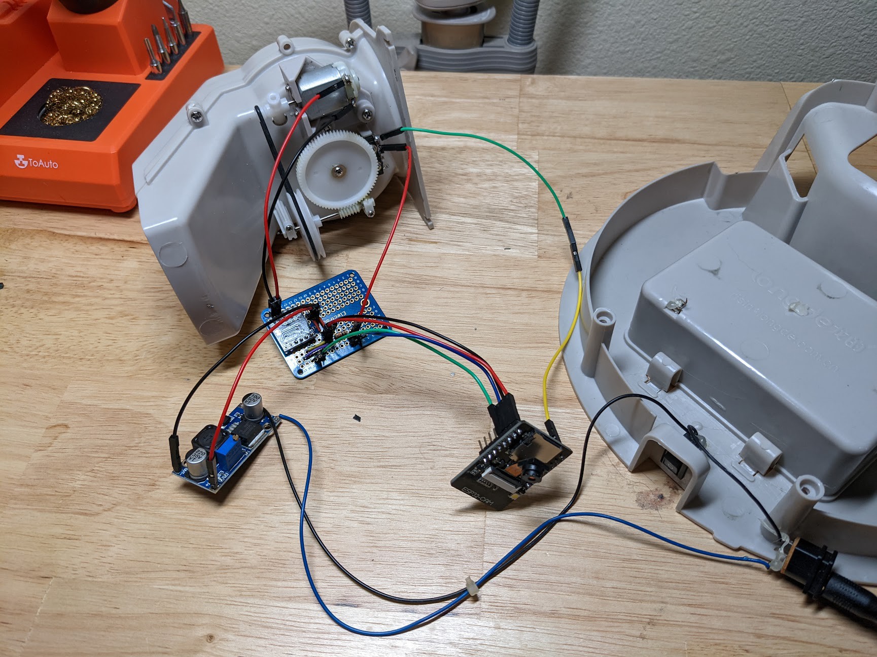
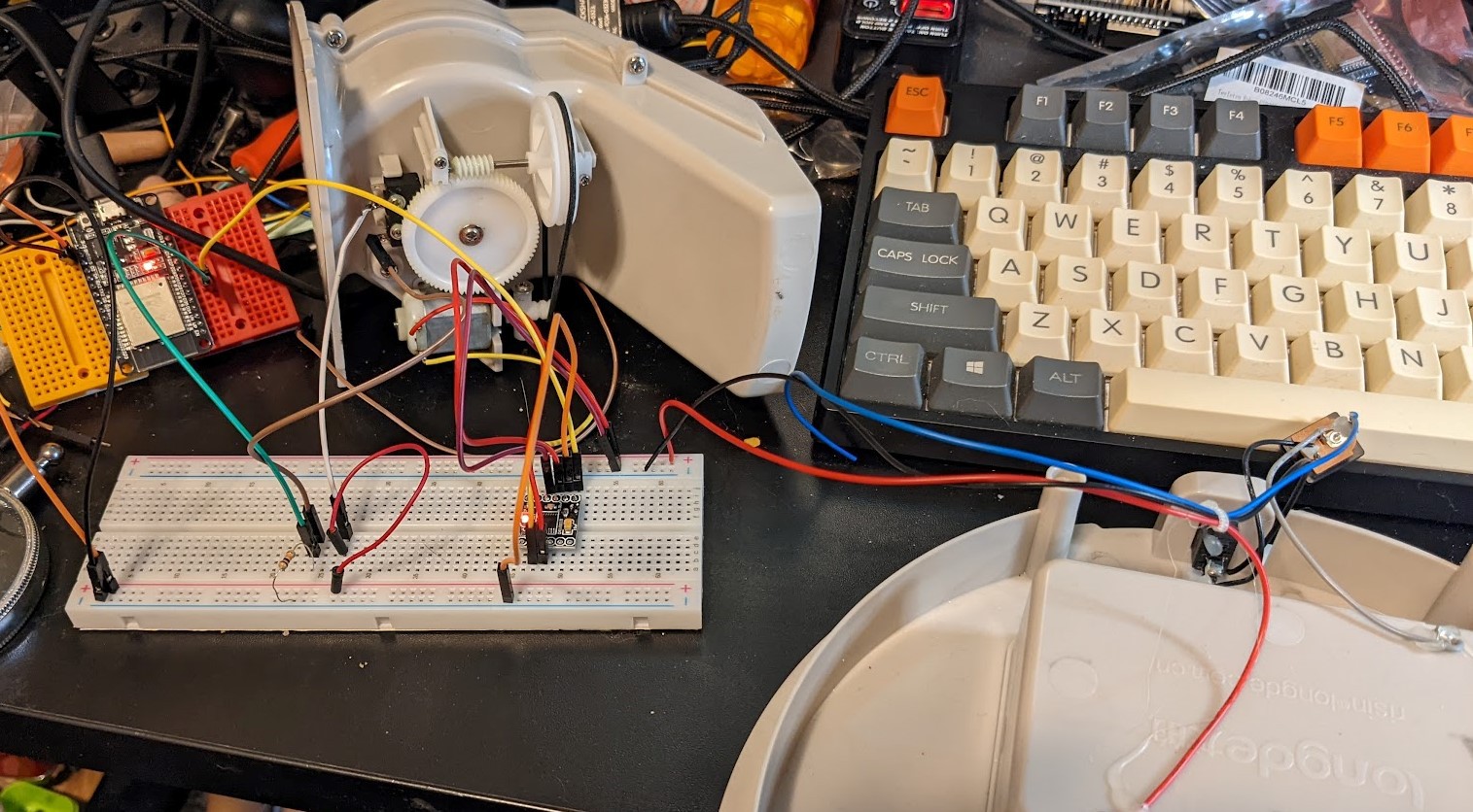
Upgrading 10 year old automated pet feeders with IoT functionality using an ESP32 microcontroler
 Bradley Austin Davis
Become a Hackaday.io member
Already have an account? Log in.
Just one more thing
To make the experience fit your profile, pick a username and tell us what interests you.
Pick an awesome username
hackaday.io/
Your profile's URL: hackaday.io/username. Max 25 alphanumeric characters.
Pick a few interests
Projects that share your interests
People that share your interests
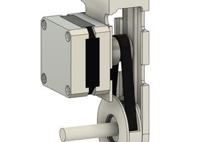
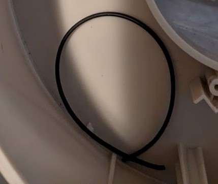 10 years in storage had caused the drive bands to lose elasticity and become brittle. They snapped on each of the 3 feeders the very first time they tried to dispense food.
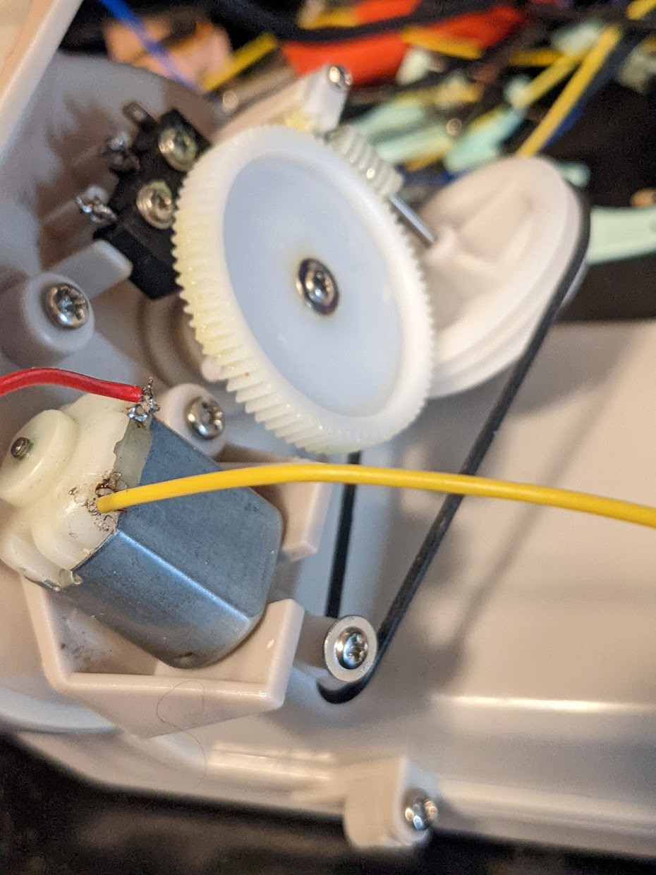
 flynnwt
 Ulrich
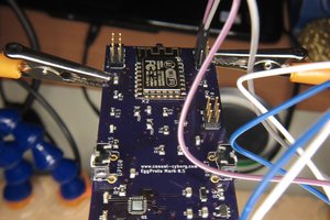
 Casual Cyborg