 Sagar 001
Hello guys, today we are going to have a look on, How I made an Arduino based FM and then turn its circuit into a fully functional PCB. In this tutorial you will learn, basic FM working, Arduino code for this FM, range, speakers, antenna and amplifiers used in this circuit. This type of digital circuits has a very big importance over any analog based circuits. It will reduce the circuitry and tuning methods.
_T1ADUc7FZD.png?auto=compress%2Cformat&w=740&h=555&fit=max)
Features:
1) Based on digital method
2) Needs very less components
3) Stereo channel availability
4) Easy to tune
5) Onboard volume control
6) Large bandwidth (50MHz to 115MHz)
7) No coils, no variable capacitors
8) Low power consumption
Fm working in brief:
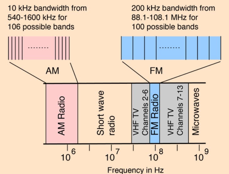
Frequency Modulation (FM) is the encoding of information in a carrier wave by changing the instantaneous frequency of the wave. FM technology is widely used in the fields of computing, telecommunications, and signal processing.
RDA5807 FM:
The RDA5807M series is the newest generation single-chip broadcast FM stereo radio tuner with fully integrated synthesizer, IF selectivity, RDS/RBDS and MPX decoder. The tuner uses the CMOS process, support multi-interface and require the least external component. All these make it very suitable for portable devices.
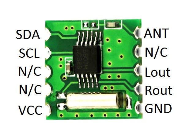
The RDA5807M series has a powerful low-IF digital audio processor, this make it have optimum sound quality with varying reception conditions. The RDA5807M series support frequency range is from 50MHz to 115MHz.
And this small module comes with a lot of features:
· CMOS single-chip fully-integrated FM tuner
· Low power consumption -Total current consumption lower than 20mA at 3.0V power supply when under normal situation
· Support worldwide frequency band 50 -115 MHz
· Support flexible channel spacing mode - 100KHz, 200KHz, 50KHz and 25KHz
· Support RDS/RBDS
· Digital low-IF tuner
· Image-reject down-converter
· High performance A/D converter
· IF selectivity performed internally
· Fully integrated digital frequency synthesizer
· Fully integrated on-chip RF and IF VCO
· Fully integrated on-chip loop filter
· Autonomous search tuning
· Support 32.768KHz crystal oscillator
· Digital auto gain control (AGC)
· Digital adaptive noise cancellation
· Soft mute
· Programmable de-emphasis (50/75 ms)
· Receive signal strength indicator (RSSI) and SNR
· Bass boost
· Volume control and mute
· Line-level analog output voltage
· Find more info from Datasheet from here, because I think this small module is full of features and that's what the technology. Changed the whole circuitry, coils, resistors and tuning capacitors into a small 0.2g 8pin SMD chip.
Breadboard circuit:
This is the circuit diagram for people, want to use Arduino nano.
Here in this circuit LM386 is used to amplify the signal, to tune the frequency 100k potentiometer is needed. 10k potentiometer is for volume. If you use custom PCB then no need to do all of this. By the way, you may try this circuit on breadboard to develop your own ideas.
All the ceramic capacitors used in this circuit are 100nf, for resistors color code is given, all the electrolytic capacitor is 1000uf.
Lm386 amplifier does not support stereo channel, this is mono channel 3W ic.
Breadboard software:
Here is our new schematics designer tool “Cirkit Designer” which is totally free to all and having a plenty of extra features over any other.
And I think cirkit designer is best software to make breadboard schematics presentation also gives you ability to view the next diagram and BOM (bill of materials). So accordingly, that you can make an estimate and present yourself good as an electronics student or hobbyist. And we are launching the simulation program this month so stay tuned.
Cirkit Designer (link to www.cirkitdesigner.com) is a one-stop-shop desktop application for designing and documenting circuits and electronics projects. With Cirkit Designer, you can lay out realistic circuit diagrams that are linked to a bill-of-materials so that you can seamlessly order the parts to your circuit.
Download cirkit designer from Here.
In the next release, Cirkit Designer is adding a code IDE with full support for compiling and programming Arduino boards, as well as a library of reference circuit designs (circuit templates including documentation, components and wiring, and code). Cirkit Designer will become the one-stop-shop to help you progress from concept to fully working breadboard prototypes.
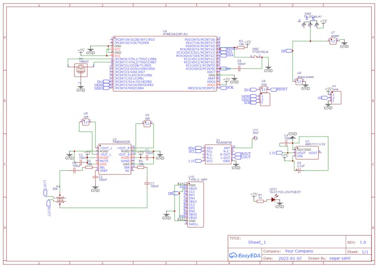
Circuit diagram:
Components required:
- Atmega328p or Arduino
- 16Mhz ceramic rasonator
- 100k,10k potentiometer
- 104 capacitor 0603
- 10k resistor 0805
- 1k resistor 0805
- C type female charging port
- reset button
- Smd led 0603
- Slide switch (ON/OFF)
- RDA5807 FM module
- PAM8403 Stereo amplifier IC
- 100uf 10volt electrolytic capacitor
- speaker and antenna
Design of custom PCB:
Download all the material regarding this project from here.

This PCB is designed in EasyEDA, I ordered this with purple solder mask. All the main components will be soldered front side and the speaker out terminals, tuning terminals, power and ICSP headers for programming is placed backside of this board.
Video & assembling:
Working of circuit:
The custom PCB has PAM8403 audio amplifier, which is a stereo amplifier and has 3+3watts output. Microcontroller atmega328p has a 16Mhz smd crystal rasonator. RDA5807 Fm and other small controlling circuitry which you can see in the circuit schematics given above. Here I am using PAM class D audio amplifier because it is low power, dual channel and 5v supported. A 50k stereo potentiometer to set the volume level.

there is no any type of programmer IC on board but ICSP is provided for programming directly using Arduino or any other MCU. C-type usb jack is only to power the FM. To tune the FM to different channels, a 100k potentiometer can be soldered on 3-pins of tune section. Which gives ability to set any channel manually.
A small slide switch is only to switch on and off the whole system. If you want to try this thing first on breadboard using simple breakout modules then go for it, circuit diagram for breadboard is given above. Testing and other instructions are provided in video.
Code:
#include <Wire.h>
    /* Select the frequency we want to tune to by way
     * of selecting the channel for the desired frequency
     */
uint16_t channel = 187;
    /*
     * assuming band starts at 87.0MHz (per settings below)
     * and channel spacing of 100kHz (0.1MHz) (per settings below)
     * then channel can be derived as follows:
     *
     * channel = (<desired freq in MHz> - 87.0) / 0.1
     *
     * which is the same as:
     * <10 x desired freq in MHz> - 870
     */
#define RDA5807M_ADDRESS  0b0010000 // 0x10
#define BOOT_CONFIG_LEN 12
#define TUNE_CONFIG_LEN 4
/*
 *  These bytes set our initial configuration
 *  We don't bother to tune to a channel at this stage.
 *  But instead initiate a reset.
 */
uint8_t boot_config[] = {
  /* register 0x02 */
  0b11000001,
    /*
     * DHIZ audio output high-z disable
     * 1 = normal operation
     *
     * DMUTE mute disable
     * 1 = normal operation
     *
     * MONO mono select
     * 0 = stereo
     *
     * BASS bass boost
     * 0 = disabled
     *
     * RCLK NON-CALIBRATE MODE
     * 0 = RCLK is always supplied
     *
     * RCLK DIRECT INPUT MODE
     * 0 = ??? not certain what this does
     *
     * SEEKUP
     * 0 = seek in down direction
     *
     * SEEK
     * 0 = disable / stop seek (i.e. don't seek)
     */
  0b00000011,
    /*
     * SKMODE seek mode:
     * 0 = wrap at upper or lower band limit and contiue seeking
     *
     * CLK_MODE clock mode
     *  000 = 32.768kHZ clock rate (match the watch cystal on the module)
     *
     * RDS_EN radio data system enable
     * 0 = disable radio data system
     *
     * NEW_METHOD use new demodulate method for improved sensitivity
     * 0 = presumably disabled
     *
     * SOFT_RESET
     * 1 = perform a reset
     *
     * ENABLE power up enable:
     * 1 = enabled
     */
  /* register 0x03 */
    /* Don't bother to tune to a channel at this stage*/
  0b00000000,
    /*
     * CHAN channel select 8 most significant bits of 10 in total
     * 0000 0000 = don't boher to program a channel at this time
     */
  0b00000000,
    /*
     * CHAN two least significant bits of 10 in total
     * 00 = don't bother to program a channel at this time
     *
     * DIRECT MODE used only when test
     * 0 = presumably disabled
     *
     * TUNE commence tune operation
     * 0 = disable (i.e. don't tune to selected channel)
     *
     * BAND band select
     * 00 = select the 87-108MHz band
     *
     * SPACE channel spacing
     * 00 = select spacing of 100kHz between channels
     */
  /* register 0x04 */
  0b00001010,
    /*
     * RESERVED 15
     * 0
     *
     * PRESUMABLY RESERVED 14
     * 0
     *
     * RESERVED 13:12
     * 00
     *
     * DE de-emphasis:
     * 1 = 50us de-emphasis as used in Australia
     *
     * RESERVED
     * 0
     *
     * SOFTMUTE_EN
     * 1 = soft mute enabled
     *
     * AFCD AFC disable
     * 0 = AFC enabled
     */
  0b00000000,
    /*
     *  Bits 7-0 are not specified, so assume all 0's
     * 0000 0000
     */
  /* register 0x05 */
  0b10001000,
    /*
     * INT_MODE
     * 1 = interrupt last until read reg 0x0C
     *
     * RESERVED 14:12
     * 000
     *
     * SEEKTH seek signal to noise ratio threshold
     * 1000 = suggested default
     */
  0b00001111,
    /*
     * PRESUMABLY RESERVED 7:6
     * 00
     *
     * RESERVED 5:4
     * 00
     *
     * VOLUME
     * 1111 = loudest volume
     */
  /* register 0x06 */
  0b00000000,
    /*
     * RESERVED 15
     * 0
     *
     * OPEN_MODE open reserved registers mode
     * 00 = suggested default
     *
     * Bits 12:8 are not specified, so assume all 0's
     * 00000
     */
  0b00000000,
    /*
     *  Bits 7:0 are not specified, so assume all 0's
     *  00000000
     */
  /* register 0x07 */
  0b01000010,
    /*
     *  RESERVED 15
     * 0
     *
     * TH_SOFRBLEND threshhold for noise soft blend setting
     * 10000 = using default value
     *
     * 65M_50M MODE
     * 1 = only applies to BAND setting of 0b11, so could probably use 0 here too
     *
     * RESERVED 8
     * 0
     */
  0b00000010,
    /*
     *  SEEK_TH_OLD seek threshold for old seek mode
     * 000000
     *
     * SOFTBLEND_EN soft blend enable
     * 1 = using default value
     *
     * FREQ_MODE
     * 0 = using defualt value
     */
};
/* After reset, we can tune the device
 * We only need program the first 4 bytes in order to do this
 */
uint8_t tune_config[] = {
  /* register 0x02 */
  0b11000000,
    /*
     * DHIZ audio output high-z disable
     * 1 = normal operation
     *
     * DMUTE mute disable
     * 1 = normal operation
     *
     * MONO mono select
     * 0 = mono
     *
     * BASS bass boost
     * 0 = disabled
     *
     * RCLK NON-CALIBRATE MODE
     * 0 = RCLK is always supplied
     *
     * RCLK DIRECT INPUT MODE
     * 0 = ??? not certain what this does
     *
     * SEEKUP
     * 0 = seek in down direction
     *
     * SEEK
     * 0 = disable / stop seek (i.e. don't seek)
     */
   0b00000001,
    /*
     * SKMODE seek mode:
     * 0 = wrap at upper or lower band limit and contiue seeking
     *
     * CLK_MODE clock mode
     * 000 = 32.768kHZ clock rate (match the watch cystal on the module)
     *
     * RDS_EN radio data system enable
     * 0 = disable radio data system
     *
     * NEW_METHOD use new demodulate method for improved sensitivity
     * 0 = presumably disabled
     *
     * SOFT_RESET
     * 0 = don't reset this time around
     *
     * ENABLE power up enable:
     * 1 = enabled
     */
   /* register 0x03 */
   /* Here's where we set the frequency we want to tune to */
   (channel >> 2),
    /* CHAN channel select 8 most significant bits of 10 in total   */
   ((channel & 0b11) << 6 ) | 0b00010000
    /*
     *  CHAN two least significant bits of 10 in total
     *
     * DIRECT MODE used only when test
     * 0 = presumably disabled
     *
     * TUNE commence tune operation
     * 1 = enable (i.e. tune to selected channel)
     *
     * BAND band select
     * 00 = select the 87-108MHz band
     *
     * SPACE channel spacing
     * 00 = select spacing of 100kHz between channels
     */
};
void setup()
{
  Serial.begin(9600);
  pinMode(A0,INPUT);
  Wire.begin();
  Wire.beginTransmission(RDA5807M_ADDRESS);
  Wire.write(boot_config, BOOT_CONFIG_LEN);
  Wire.endTransmission();
  Wire.beginTransmission(RDA5807M_ADDRESS);
  Wire.write(tune_config, TUNE_CONFIG_LEN);
  Wire.endTransmission();
}//setup end
void loop()
{
  int channel1 =90,newA;
  static int oldA = 0; // set the oldA as HIGH
  int result = 0;
  newA = analogRead(A0);
  if ((newA - oldA) > 10 || (oldA - newA) > 10){
    Serial.println(newA);
    if(newA!= oldA){
      channel = channel1+(newA/10);
      myChangeChannel(channel);
      oldA=newA;
      }
}
  uint16_t frequency = channel+870;
  uint16_t num1 = (frequency / 1000) % 10;
  uint16_t num2 = (frequency / 100) % 10;
  uint16_t num3 = (frequency / 10) % 10;
  uint16_t num4 = frequency % 10;
  Serial.print(num1);
  Serial.print(num2);
  Serial.print(num3);
  Serial.print(num4);
  Serial.print("--");
  Serial.println(channel+870);
}//loop end
/*
 * Function to change channel on radio RDA5807
 * Example: channel = 191
 */
void myChangeChannel(int channel){ /* void if nothing is returned else int */
  /*
   * first write new channel to tune_config massive
   */
   tune_config[2] = (channel >> 2);
   tune_config[3] = ((channel & 0b11) << 6 ) | 0b00010000;
      Wire.begin();
      Wire.beginTransmission(RDA5807M_ADDRESS);
      Wire.write(tune_config, TUNE_CONFIG_LEN);
      Wire.endTransmission();
  }
JLCPCB:
JLCPCB is the one of the most popular PCB makers. Price is just $2 for 2, 4 and 6 layer PCB. They just launched new purple solder mask, aluminum Pcb and 3d printing service in very low cost. Pcb quality is not compromised at any cost. Check them out right now from Here.

JLCPCB Is also providing new user coupons and sign-up rewards of up to $30. So, check them out from here. Register using this link to get Free PCB assembly service coupons. Get your 2 layer to 6-layer PCB’s just in $2, stencil and PCB assembly service in just $7.
For PC: https://jlcpcb.com/SSRFor mobile phone: http://m.jlcpcb.com/ssi

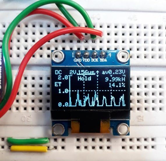
Updates:
In the next updates I will try to add a screen, basically a OLED which can display channel frequency, volume and battery percentage. I will try to minimize the circuit and a less power microcontroller.
More projects:
1) How to make Arduino Uno clone board.
2) How to program Arduino Using Smart Phone.
3) Arduino Nano clone board problems and solutions.
4) How to make Inductance Meter Using Arduino.
5) Raspberry Pi- PICO Oscilloscope.
Think you enjoy my work, stay tuned. Follow us on Instagram (sagar_saini_7294) and hackaday.
please support us- No donations, just follow and leave a comment.