Sagar 001
Hello guys, today we are going to have a look on, How I made an Arduino based FM and then turn its circuit into a fully functional PCB. In this tutorial you will learn, basic FM working, Arduino code for this FM, range, speakers, antenna and amplifiers used in this circuit. This type of digital circuits has a very big importance over any analog based circuits. It will reduce the circuitry and tuning methods.
_T1ADUc7FZD.png?auto=compress%2Cformat&w=740&h=555&fit=max)
Features:
1) Based on digital method
2) Needs very less components
3) Stereo channel availability
4) Easy to tune
5) Onboard volume control
6) Large bandwidth (50MHz to 115MHz)
7) No coils, no variable capacitors
8) Low power consumption
Fm working in brief:
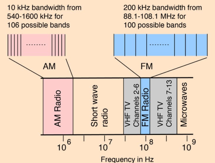
Frequency Modulation (FM) is the encoding of information in a carrier wave by changing the instantaneous frequency of the wave. FM technology is widely used in the fields of computing, telecommunications, and signal processing.
RDA5807 FM:
The RDA5807M series is the newest generation single-chip broadcast FM stereo radio tuner with fully integrated synthesizer, IF selectivity, RDS/RBDS and MPX decoder. The tuner uses the CMOS process, support multi-interface and require the least external component. All these make it very suitable for portable devices.
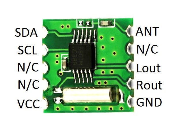
The RDA5807M series has a powerful low-IF digital audio processor, this make it have optimum sound quality with varying reception conditions. The RDA5807M series support frequency range is from 50MHz to 115MHz.
And this small module comes with a lot of features:
· CMOS single-chip fully-integrated FM tuner
· Low power consumption -Total current consumption lower than 20mA at 3.0V power supply when under normal situation
· Support worldwide frequency band 50 -115 MHz
· Support flexible channel spacing mode - 100KHz, 200KHz, 50KHz and 25KHz
· Support RDS/RBDS
· Digital low-IF tuner
· Image-reject down-converter
· High performance A/D converter
· IF selectivity performed internally
· Fully integrated digital frequency synthesizer
· Fully integrated on-chip RF and IF VCO
· Fully integrated on-chip loop filter
· Autonomous search tuning
· Support 32.768KHz crystal oscillator
· Digital auto gain control (AGC)
· Digital adaptive noise cancellation
· Soft mute
· Programmable de-emphasis (50/75 ms)
· Receive signal strength indicator (RSSI) and SNR
· Bass boost
· Volume control and mute
· Line-level analog output voltage
· Find more info from Datasheet from here, because I think this small module is full of features and that's what the technology. Changed the whole circuitry, coils, resistors and tuning capacitors into a small 0.2g 8pin SMD chip.
Breadboard circuit:
This is the circuit diagram for people, want to use Arduino nano.
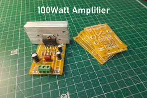
Here in this circuit LM386 is used to amplify the signal, to tune the frequency 100k potentiometer is needed. 10k potentiometer is for volume. If you use custom PCB then no need to do all of this. By the way, you may try this circuit on breadboard to develop your own ideas.
All the ceramic capacitors used in this circuit are 100nf, for resistors color code is given, all the electrolytic capacitor is 1000uf.
Lm386 amplifier does not support stereo channel, this is mono channel 3W ic.
Breadboard software:
Here is our new schematics designer tool “Cirkit Designer” which is totally free to all and having a plenty of extra features over any other.
And I think cirkit designer is best software to make breadboard schematics presentation also gives you ability to view the next diagram and BOM (bill of materials). So accordingly, that you can make an estimate and present yourself good as an electronics student or hobbyist. And we are launching the simulation program this month so stay tuned.
Cirkit Designer (link to www.cirkitdesigner.com) is a one-stop-shop desktop application for designing and documenting...
Read more »
 ElectroBoy
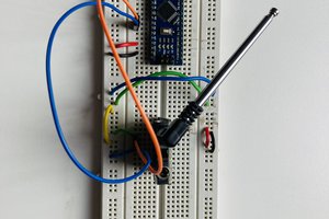
 Xtreme Tech