mircemk
PEMF therapy improves sleep, mental focus, and the body’s overall performance by helping the energy output and regeneration of the body’s cells.
Clinical studies have demonstrated that PEMFs are capable of:
- Increasing circulation
- Decreasing inflammation
- Accelerating bone healing
- Enhancing muscle function
- Reducing the effects of stress
- Improving blood oxygenation, and much morе
In several of my previous videos I have presented you with simple ways to make this type of device without any great knowledge in the field of electronics. Commercial such devices are sold at a price of several hundred to thousands of dollars, so my goal is to make the simple to build and functional device available to more people who can not afford it.
This time I will also show you a simple way to make a High Power PEMF device, which gives a magnetic flux density that is about 10 times stronger than that of previous devices.
There are two options for building such a device:
1. Increase the supply voltage to approximately 50-70V and a current of 3-5A, thereby increasing the ohmic resistance of the Coil.
2. Use a standard power supply from an old PC (12V / 20A), and reduce the ohmic resistance of the coil.
The first way is impractical due to the fact that it uses a non-standard power supply that is difficult to obtain, the schematic diagram would be much more complicated due to the use of two voltage regulators, and also a voltage of 70 Volts and more is potentially dangerous. The second way has none of these disadvantages, it is easier to make and uses components that are much easier to obtain.
The device is very simple to build and contains the following components:
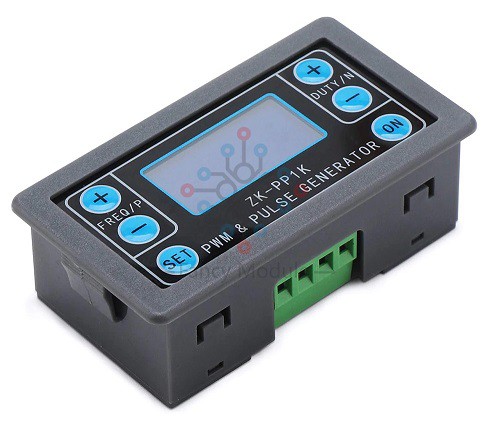
- PWM Signal generator module ZK-PP1K (Also, you can use any of the signal generator modules used in my previous PEMF projects)
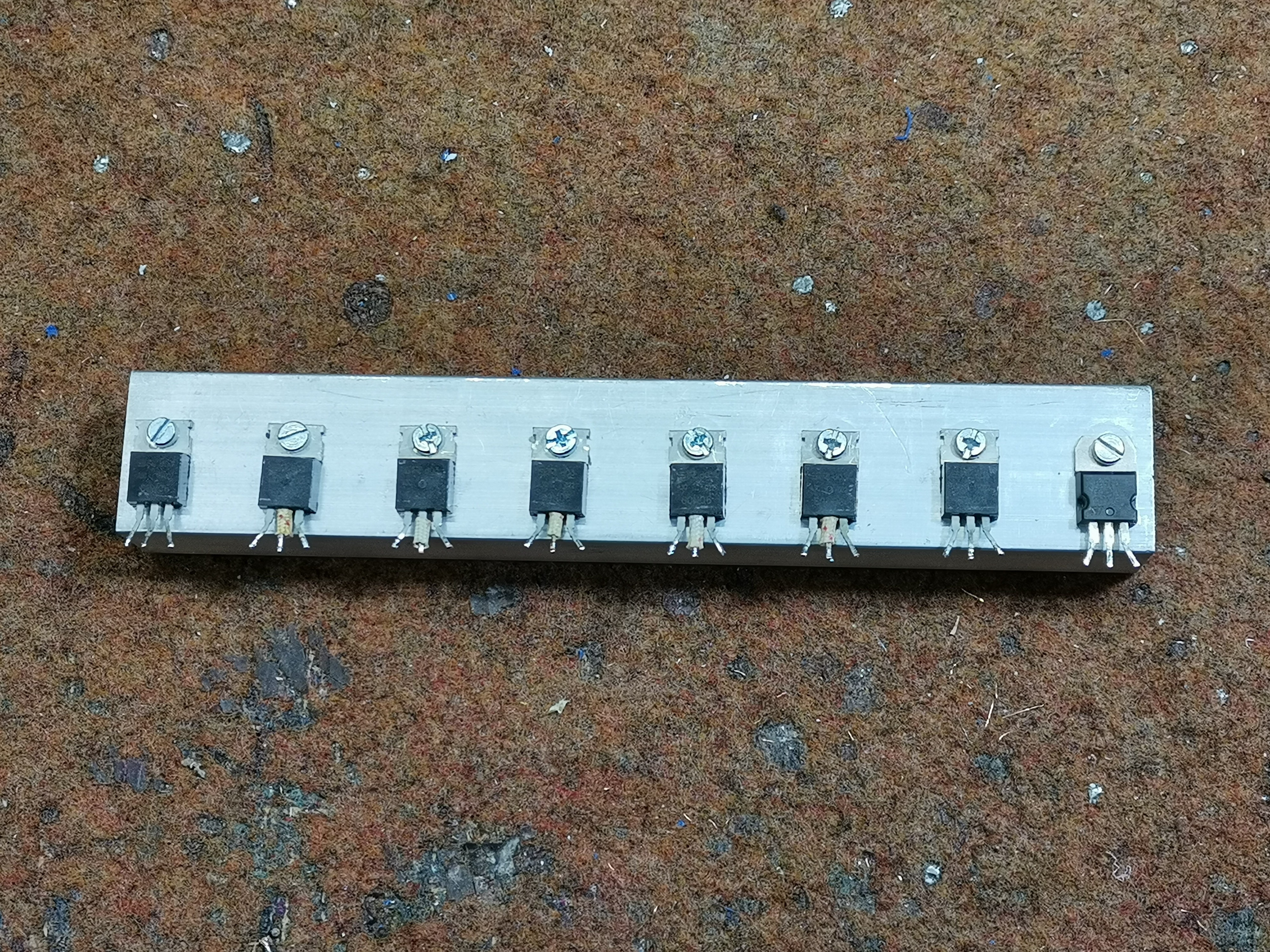
- 8 pcs. cheap N-channel Power mosfet transistors (in my case P50N06 , but you can use any other mosfet with similar characteristics). You can get 10 pieces at a price of 2 dollars in total.
- 10К Potentiometer
- Resistor 100 Ohm - 8 pcs.
- 3A diode
- Power supply unit from old PC (I use this PSU from Server PC, but you can use standard PSU from home PC)
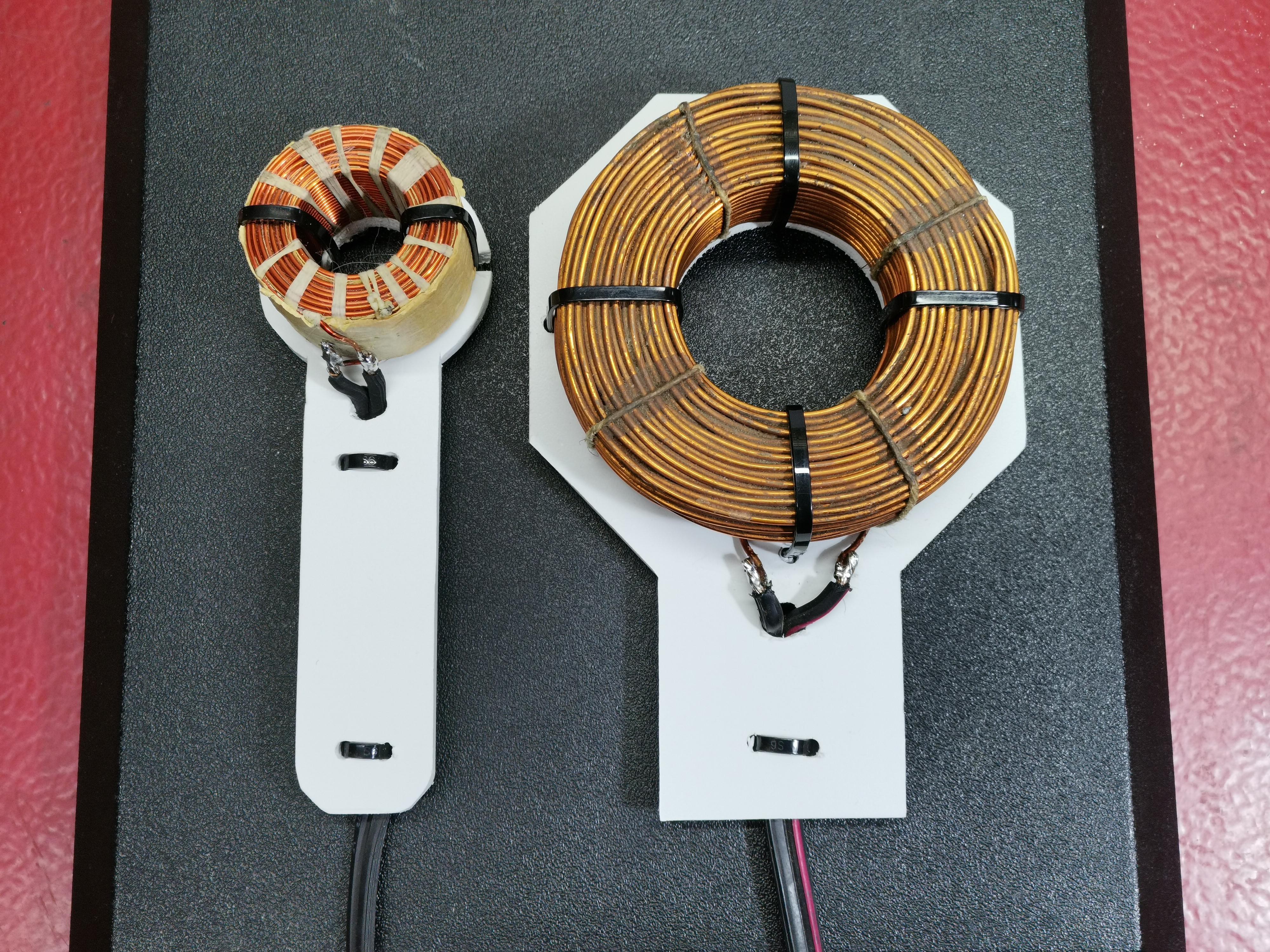
- and The coil that generates the magnetic flux
The Mosfets are mounted on a sufficiently massive Aluminum cooler without insulation, because the Drain electrodes of each transistor are interconnected. The interconnections should be made with a suitable wires with a cross section of at least 2.5 mm, because a very strong current flows through them.
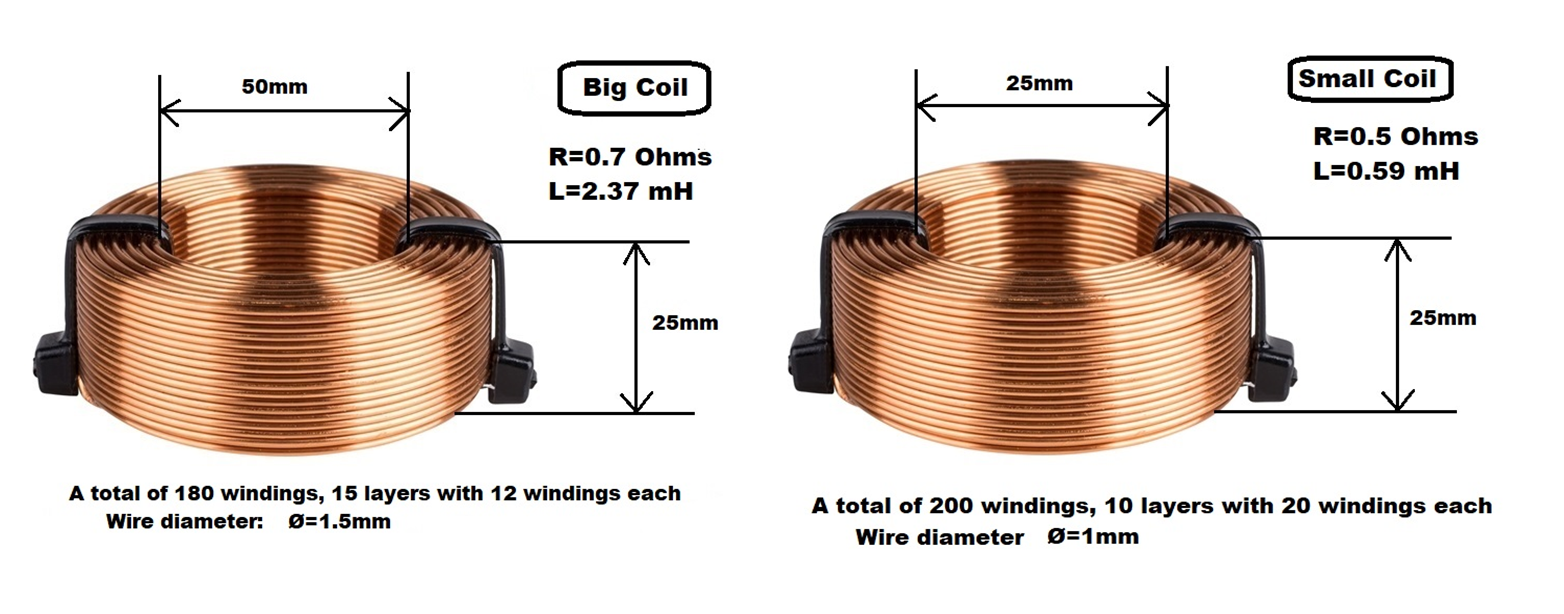
Special attention should be paid to the construction of the coils because the Mosfet can burn very easily. That's why I made detailed drawings with the dimensions of the coils and the wire. Of course, coils with other dimensions can be made, but two conditions must be met:
- The cross section of the wire must not be less than 1 mm
- The ohmic resistance of the coil must not be less than 0.5 ohms
- The inductance of the coil should not be less than 0.5 mH
When the device is switched on, "Pulse" Led starts flashing at a frequency set by the signal generator. Based on the instructions of many manufacturers of such devices, this frequency should be in the range of 4 to 30 Hz and a duty cycle with a value of 5% to 15%. The potentiometer controls the intensity of the magnetic flux, and its strength is proportional to the intensity of the Led. Now to demonstrate the strength of the magnetic flux, we will do a little experiment. We pass a small permanent magnet through the torus. Under the action of a strong magnetic field, the magnet is cracked by the coil. This effect is used in...
Read more »