 kelvinA
[C] = Code project log
With the requirement of research for #SecSavr Suspense [gd0105] dwindling down, I'm starting to suspect that all my projects seem to slow down or stall because of Fusion360. I'm wondering if it's just modelling in CAD in general, but I don't like the idea of spending 10s of hours in Fusion for what I think should take 1/10th the time. Even if I get to the other side with a completed model, projects like #Revolving Hotend [gd0012] just take a hard stall straight after and this seemingly random phenomenon could actually be attributed to all my mental energy being spent on Fusion360!
My research concludes that creating a new CAD package is a long and multi-year process, and I don't really have that kind of time, so I'm hoping to meet in the middle somewhere and feed my custom stuff with all the instructions into a Fusion360 plugin, kind of like Grasshopper or CAD Sketcher.
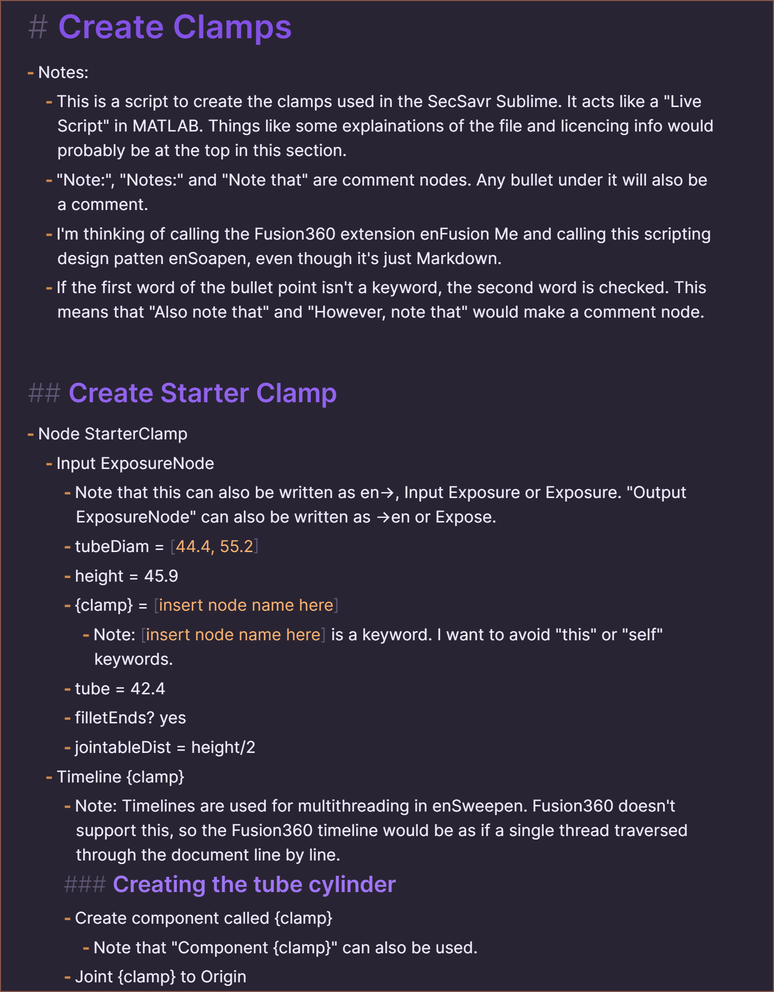
Suprisingly, searching "markdown based CAD" on the internet produces no relevant results. I was under the impression that, similar to many things being written in JavaScript, if a task is doable in text it's been done in Markdown. So I opened Obsidian and got to writing some clamps I modelled for gd0036. Here's the raw:
# Create Clamps
- Notes:
- This is a script to create the clamps used in the SecSavr Sublime. It acts like a "Live Script" in MATLAB. Things like some explainations of the file and licencing info would probably be at the top in this section.
- "Note:", "Notes:" and "Note that" are comment nodes. Any bullet under it will also be a comment.
- I'm thinking of calling the Fusion360 extension enFusion Me and calling this scripting design patten enSoapen, even though it's just Markdown.
- If the first word of the bullet point isn't a keyword, the second word is checked. This means that "Also note that" and "However, note that" would make a comment node.
## Create Starter Clamp
- Node StarterClamp
- Input ExposureNode
- Note that this can also be written as en->, Input Exposure or Exposure. "Output ExposureNode" can also be written as ->en or Expose.
- tubeDiam = [44.4, 55.2]
- height = 45.9
- {clamp} = [insert node name here]
- Note: [insert node name here] is a keyword. I want to avoid "this" or "self" keywords.
- tube = 42.4
- filletEnds? yes
- jointableDist = height/2
- Timeline {clamp}
- Note: Timelines are used for multithreading in enSweepen. Fusion360 doesn't support this, so the Fusion360 timeline would be as if a single thread traversed through the document line by line.
### Creating the tube cylinder
- Create component called {clamp}
- Note that "Component {clamp}" can also be used.
- Joint {clamp} to Origin
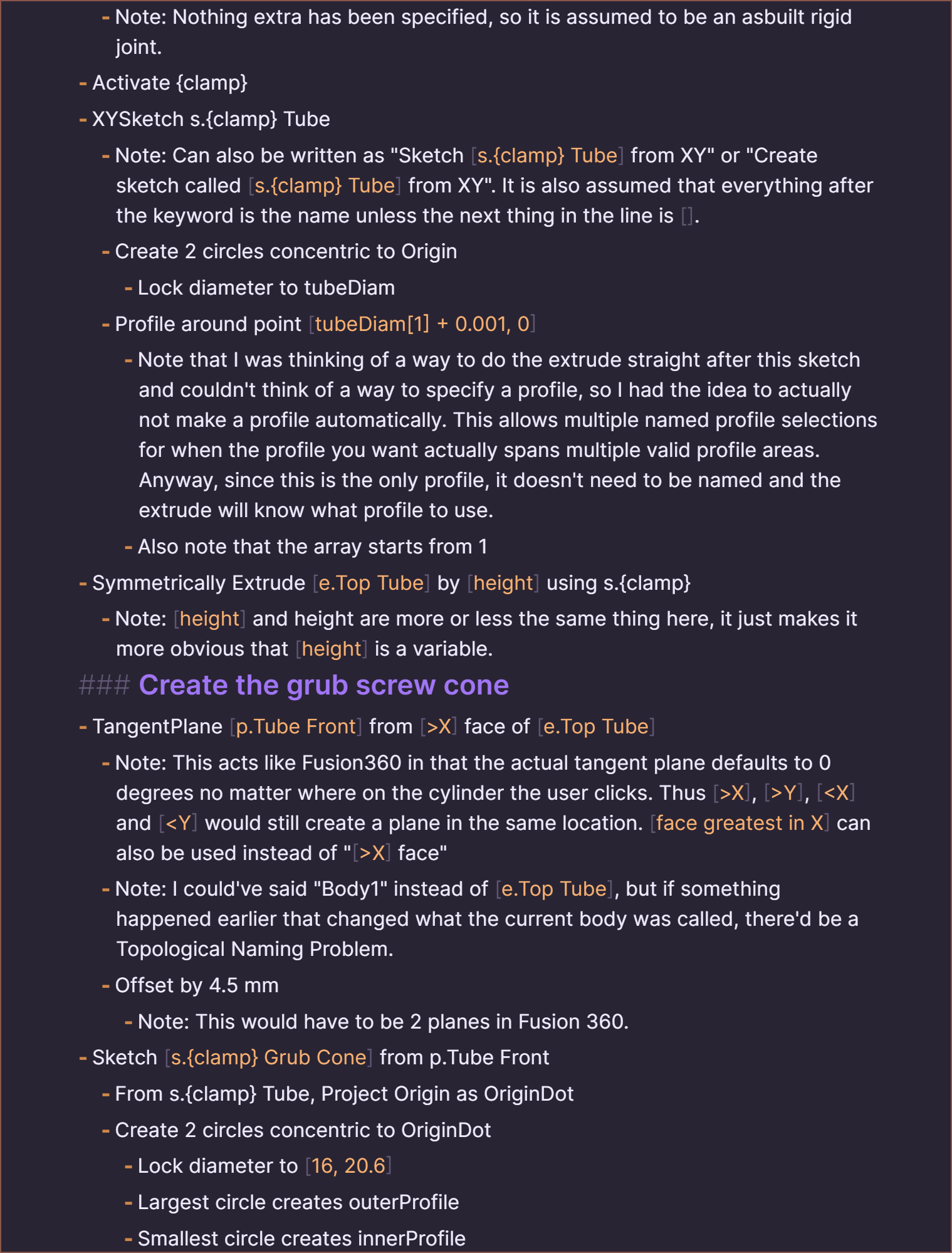
- Note: Nothing extra has been specified, so it is assumed to be an asbuilt rigid joint.
- Activate {clamp}
- XYSketch s.{clamp} Tube
- Note: Can also be written as "Sketch [s.{clamp} Tube] from XY" or "Create sketch called [s.{clamp} Tube] from XY". It is also assumed that everything after the keyword is the name unless the next thing in the line is [].
- Create 2 circles concentric to Origin
- Lock diameter to tubeDiam
- Profile around point [tubeDiam[1] + 0.001, 0]
- Note that I was thinking of a way to do the extrude straight after this sketch and couldn't think of a way to specify a profile, so I had the idea to actually not make a profile automatically. This allows multiple named profile selections for when the profile you want actually spans multiple valid profile areas. Anyway, since this is the only profile, it doesn't need to be named and the extrude will know what profile to use.
- Also note that the array starts from 1
- Symmetrically Extrude [e.Top Tube] by [height] using s.{clamp}
- Note: [height] and height are more or less the same thing here, it just makes it more obvious that [height] is a variable.
### Create the grub screw cone
- TangentPlane [p.Tube Front] from [>X] face of [e.Top Tube]
- Note: This acts like Fusion360 in that the actual tangent plane defaults to 0 degrees no matter where on the cylinder the user clicks. Thus [>X], [>Y], [X] face"
- Note: I could've said "Body1" instead of [e.Top Tube], but if something happened earlier that changed what the current body was called, there'd be a Topological Naming Problem.
- Offset by 4.5 mm
- Note: This would have to be 2 planes in Fusion 360.
- Sketch [s.{clamp} Grub Cone] from p.Tube Front
- From s.{clamp} Tube, Project Origin as OriginDot
- Create 2 circles concentric to OriginDot
- Lock diameter to [16, 20.6]
- Largest circle creates outerProfile
- Smallest circle creates innerProfile
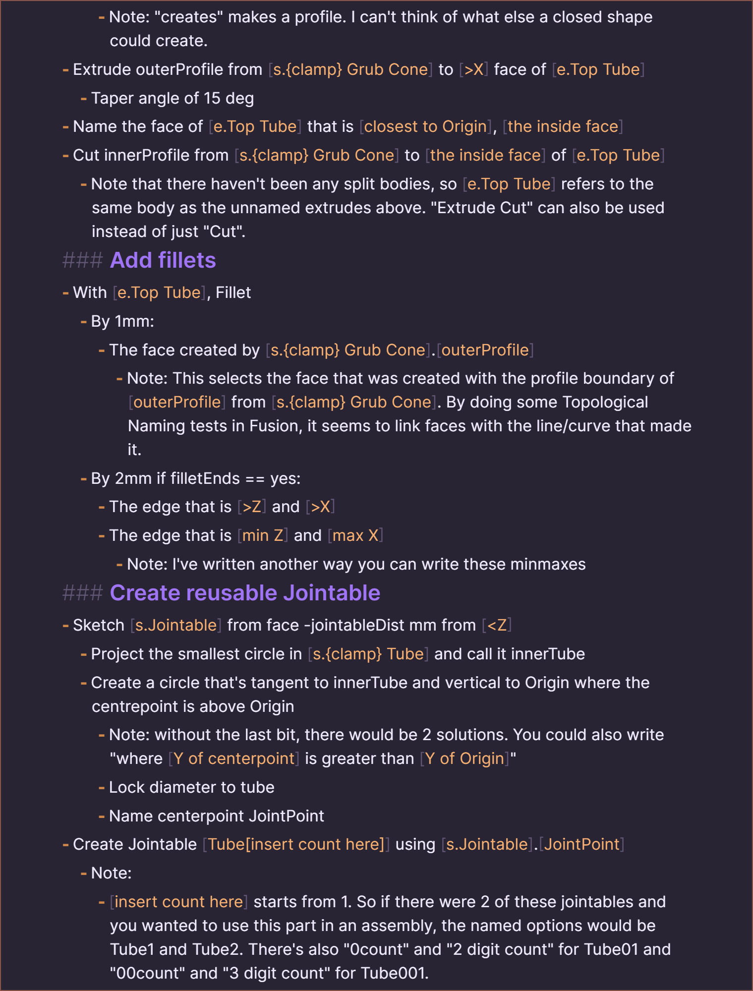
- Note: "creates" makes a profile. I can't think of what else a closed shape could create.
- Extrude outerProfile from [s.{clamp} Grub Cone] to [>X] face of [e.Top Tube]
- Taper angle of 15 deg
- Name the face of [e.Top Tube] that is [closest to Origin], [the inside face]
- Cut innerProfile from [s.{clamp} Grub Cone] to [the inside face] of [e.Top Tube]
- Note that there haven't been any split bodies, so [e.Top Tube] refers to the same body as the unnamed extrudes above. "Extrude Cut" can also be used instead of just "Cut".
### Add fillets
- With [e.Top Tube], Fillet
- By 1mm:
- The face created by [s.{clamp} Grub Cone].[outerProfile]
- Note: This selects the face that was created with the profile boundary of [outerProfile] from [s.{clamp} Grub Cone]. By doing some Topological Naming tests in Fusion, it seems to link faces with the line/curve that made it.
- By 2mm if filletEnds == yes:
- The edge that is [>Z] and [>X]
- The edge that is [min Z] and [max X]
- Note: I've written another way you can write these minmaxes
### Create reusable Jointable
- Sketch [s.Jointable] from face -jointableDist mm from [
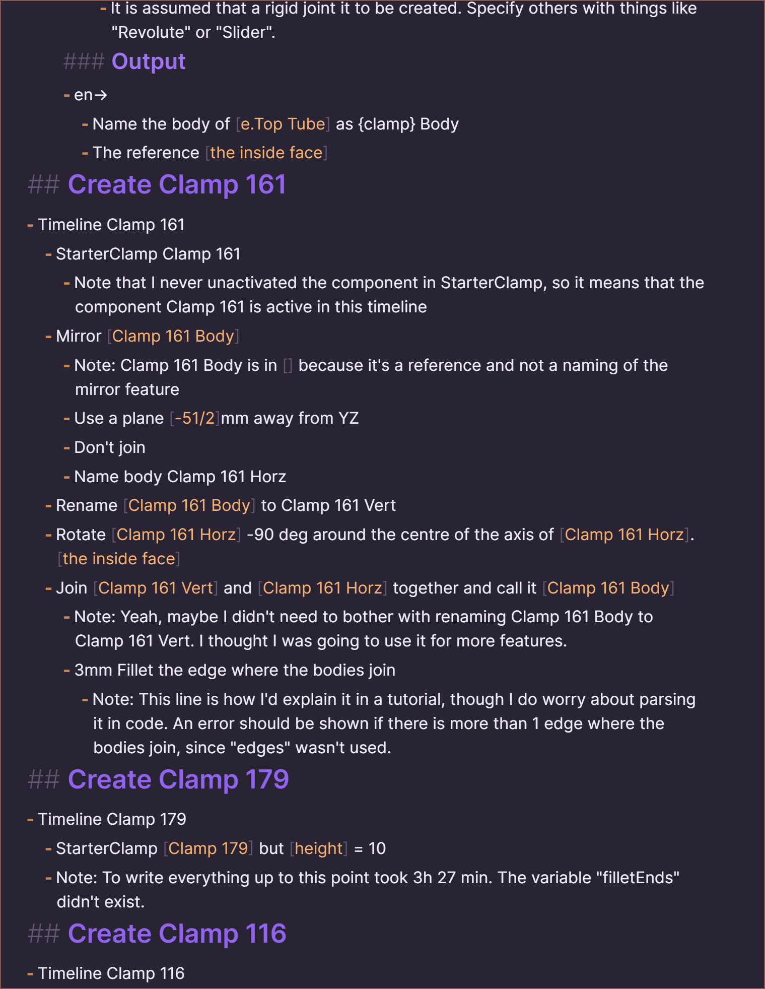
- Name the body of [e.Top Tube] as {clamp} Body
- The reference [the inside face]
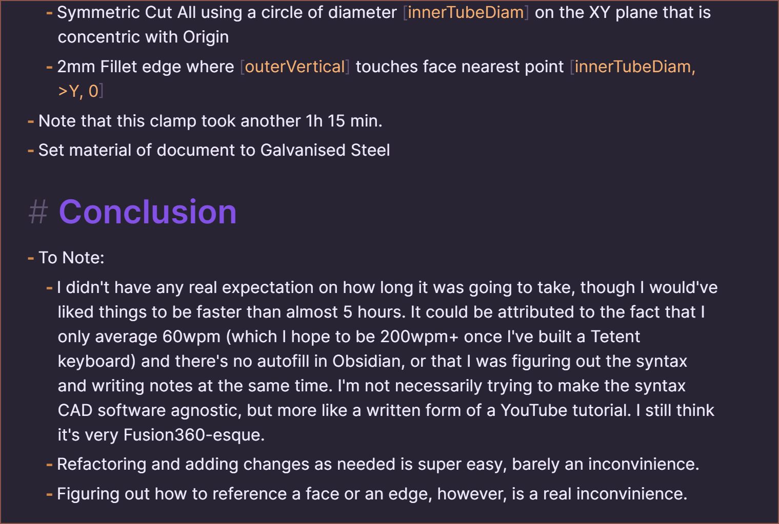
## Create Clamp 161
- Timeline Clamp 161
- StarterClamp Clamp 161
- Note that I never unactivated the component in StarterClamp, so it means that the component Clamp 161 is active in this timeline
- Mirror [Clamp 161 Body]
- Note: Clamp 161 Body is in [] because it's a reference and not a naming of the mirror feature
- Use a plane [-51/2]mm away from YZ
- Don't join
- Name body Clamp 161 Horz
- Rename [Clamp 161 Body] to Clamp 161 Vert
- Rotate [Clamp 161 Horz] -90 deg around the centre of the axis of [Clamp 161 Horz].[the inside face]
- Join [Clamp 161 Vert] and [Clamp 161 Horz] together and call it [Clamp 161 Body]
- Note: Yeah, maybe I didn't need to bother with renaming Clamp 161 Body to Clamp 161 Vert. I thought I was going to use it for more features.
- 3mm Fillet the edge where the bodies join
- Note: This line is how I'd explain it in a tutorial, though I do worry about parsing it in code. An error should be shown if there is more than 1 edge where the bodies join, since "edges" wasn't used.
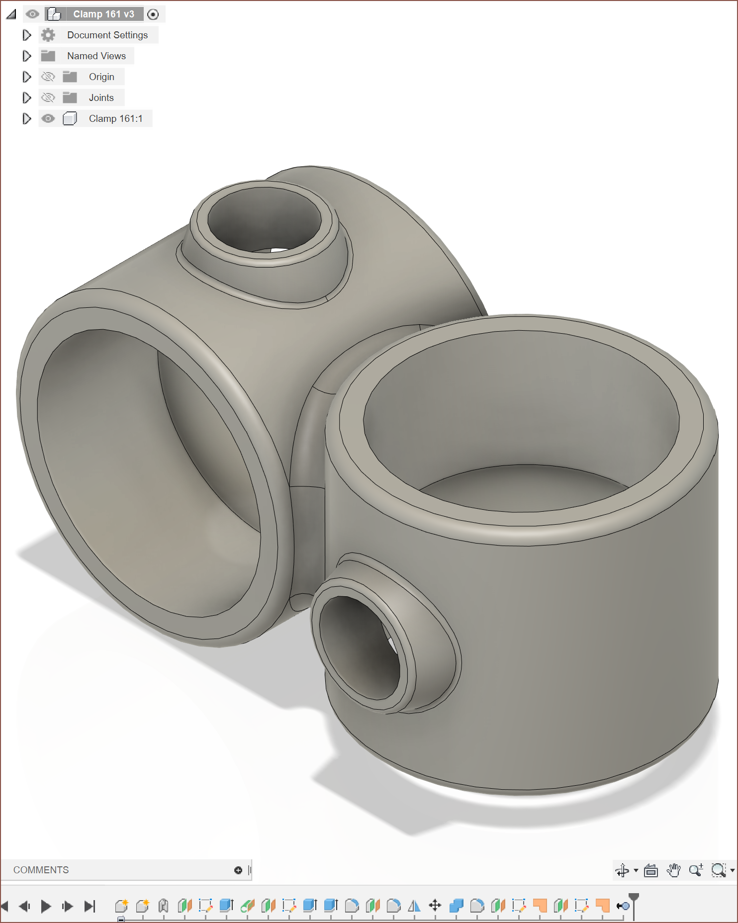
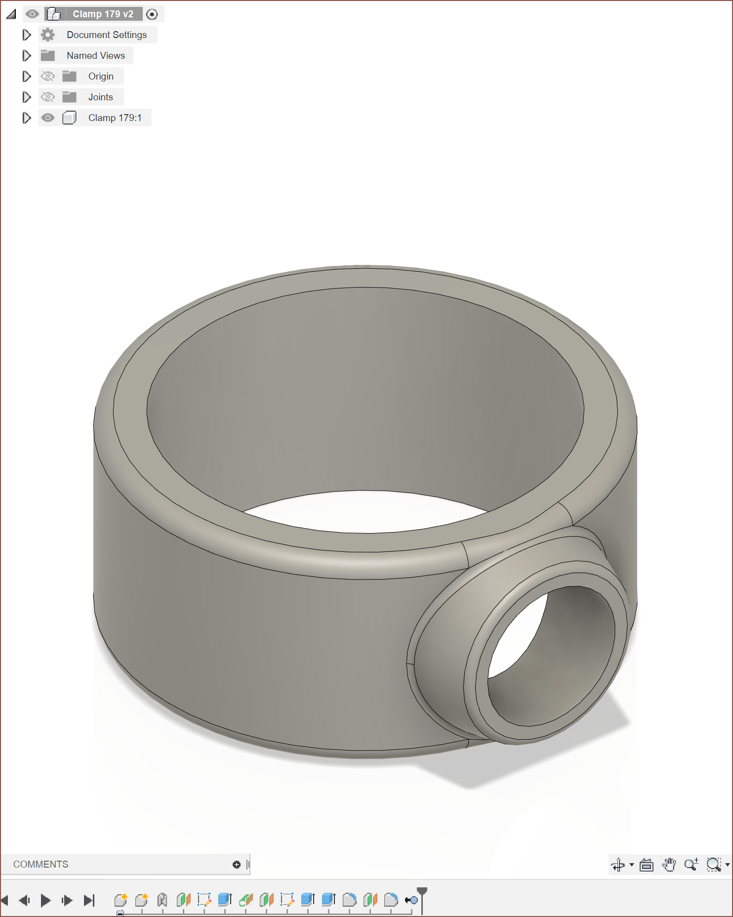
## Create Clamp 179
- Timeline Clamp 179
- StarterClamp [Clamp 179] but [height] = 10
- Note: To write everything up to this point took 3h 27 min. The variable "filletEnds" didn't exist.
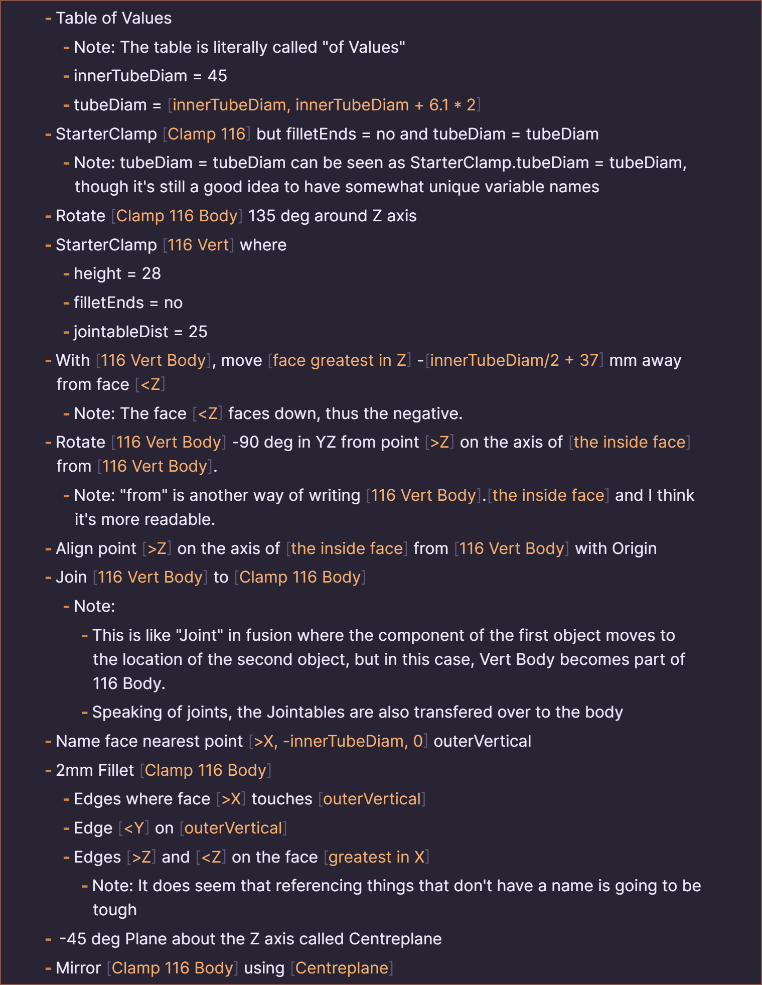
## Create Clamp 116
- Timeline Clamp 116
- Table of Values
- Note: The table is literally called "of Values"
- innerTubeDiam = 45
- tubeDiam = [innerTubeDiam, innerTubeDiam + 6.1 * 2]
- StarterClamp [Clamp 116] but filletEnds = no and tubeDiam = tubeDiam
- Note: tubeDiam = tubeDiam can be seen as StarterClamp.tubeDiam = tubeDiam, though it's still a good idea to have somewhat unique variable names
- Rotate [Clamp 116 Body] 135 deg around Z axis
- StarterClamp [116 Vert] where
- height = 28
- filletEnds = no
- jointableDist = 25
- With [116 Vert Body], move [face greatest in Z] -[innerTubeDiam/2 + 37] mm away from face [Z] on the axis of [the inside face] from [116 Vert Body].
- Note: "from" is another way of writing [116 Vert Body].[the inside face] and I think it's more readable.
- Align point [>Z] on the axis of [the inside face] from [116 Vert Body] with Origin
- Join [116 Vert Body] to [Clamp 116 Body]
- Note:
- This is like "Joint" in fusion where the component of the first object moves to the location of the second object, but in this case, Vert Body becomes part of 116 Body.
- Speaking of joints, the Jointables are also transfered over to the body
- Name face nearest point [>X, -innerTubeDiam, 0] outerVertical
- 2mm Fillet [Clamp 116 Body]
- Edges where face [>X] touches [outerVertical]
- Edge [Z] and [Y, 0]
- Note that this clamp took another 1h 15 min.
- Set material of document to Galvanised Steel
# Conclusion
- To Note:
- I didn't have any real expectation on how long it was going to take, though I would've liked things to be faster than almost 5 hours. It could be attributed to the fact that I only average 60wpm (which I hope to be 200wpm+ once I've built a Tetent keyboard) and there's no autofill in Obsidian, or that I was figuring out the syntax and writing notes at the same time. I'm not necessarily trying to make the syntax CAD software agnostic, but more like a written form of a YouTube tutorial. I still think it's very Fusion360-esque.
- Refactoring and adding changes as needed is super easy, barely an inconvinience.
- Figuring out how to reference a face or an edge, however, is a real inconvinience.
Here's what I see in Obsidian:
And here is the intended results (minus the Fusion360 group stuff like the temp component created at the start and deleted at the end):
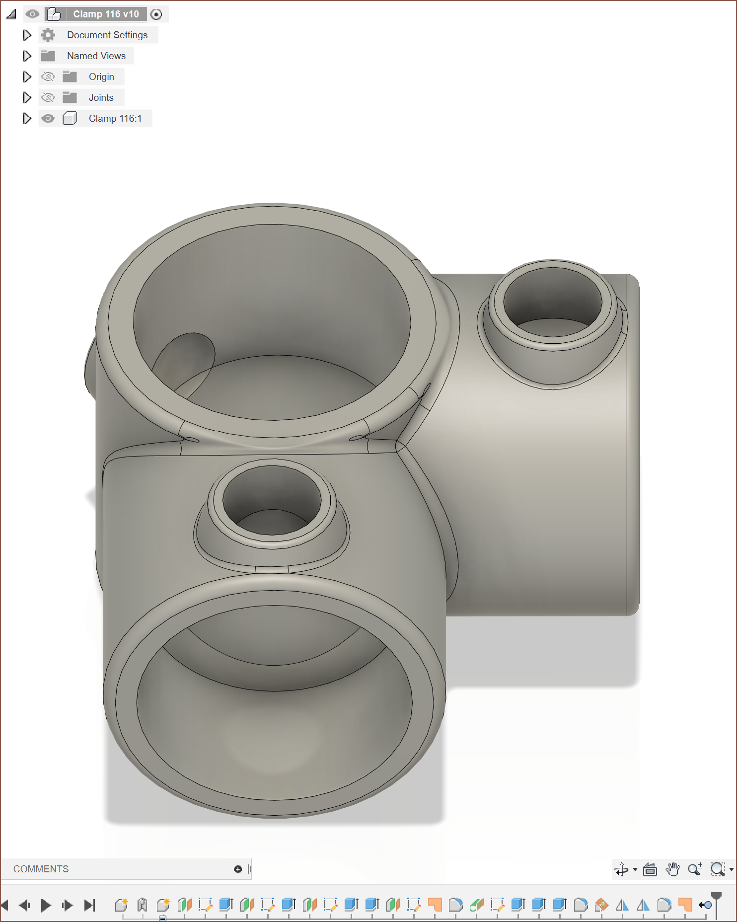
It's 2:38am right now, so I'm too tired to make sure the syntax is completely consistent, but this should give anyone reading an idea as to what I'm envisioning.
For reference of time:
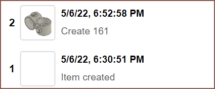
Clamp 161: 22 minutes
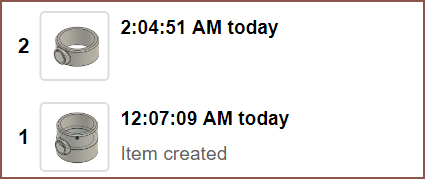
Clamp 179: I think about 2 mins
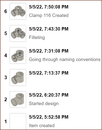
Clamp 116: About 1h 45 min
Discussions
Become a Hackaday.io Member
Create an account to leave a comment. Already have an account? Log In.
Essentially, the idea is to write the file in a way that sounds like a SolidEdge tutorial: https://solidedge.siemens.com/en/resource/tutorial/fidget-spinner/#part-1
This is so that if someone wanted to create the part in other software, they'd just need to read it as if it was a step-by-step tutorial.
Are you sure? yes | no
"Node" nodes are custom features. Every file is also a Node.
Are you sure? yes | no
Read it over today and have some changes:
- To name Mirror features, use "Name this feature" in the node. Thus Mirror [insert feature name here] always refers to the body of [insert feature name here] instead of naming the Mirror. I'm also thinking of using "uses" to remove ambiguity between naming a feature and using a feature, such as "Extrude [extrudename] uses [profile name] from..."
- Changed the TangentPlane line to "TangentPlane [p.Tube Front] is 4.5 mm from [>X] face of [e.Top Tube]"
- Changed the extrude that uses outerProfile to "Extrude outerProfile from [s.{clamp} Grub Cone] to [greatest X] face of [e.Top Tube] with a taper angle of 15 deg". Additionally, I'm thinking of using brackets. If there's only 1 face called outerProfile in the entire active component, the "from" shouldn't be needed. Lastly, for readablility, I'm thinking of "Extrude outerProfile (from [s.{clamp} Grub Cone]) to..."
- Changed the line under that to "Name the face of [e.Top Tube] that is [closest to Origin] "the inside face""
- Output is supposed to be ->en not en->
- Removed "The reference" from [the inside face] in the output exposurenode
Are you sure? yes | no