 kelvinA
Some history
The Coaxial8or has been installed and now it's time for me to get the new electrical system set up so that I can heat up the CHC Pro and unscrew the heatbreak and nozzle that are both currently attached to it.
If you've been reading those logs, you may remember that my PSU popped a fuse. I didn't know if it was the suspicious PSU itself that's been sitting in the open in a cupboard for years or the shady mains kettle switch socket, so replacements for both have arrived in the mail. I'm partway though the upgrade when writing this intro, and it was the switch socket's fuse that has blown.
I decided to finally look into installing safety related features for the bed before I power the printer back on. I don't think I remembered to mention this anywhere, but when I was working on the CR600S and my arm lightly grazed the edge of the spring steel bed, it felt a lot sharper than it should have. I got a multimeter to it and left ground floating, and I was getting as much as 18VAC, down to 4AC when the bed was powered. My current hypothesis is that the (reverse order) stackup of
- [conductive heating wire]
- [silicone insulation]
- [conductive aluminium bed]
- [insulating magnetic sheet]
- [conductive underside of spring steel plate]
is acting like a capacitor.
Unintentional potential differences like this is why earthing bonding wire is needed for things like plumbing. Me In The Past knew that, for safety, I should earth the AC bed when I installed it, but quickly dismissed the idea because I had neither the tools nor any free tapping locations to screw a bonding wire in. It didn't help that I couldn't (and still can't, hence this log) find any strategies for grounding a CR-10 / Ender3 bed (with or without an AC silicone mat installed).
Well a few weeks ago, I came to the simple conclusion to just use one of the 4 M4 tramming bolts that are already there.
Installing the upgrade
To facilitate this upgrade, I've gotten the following:
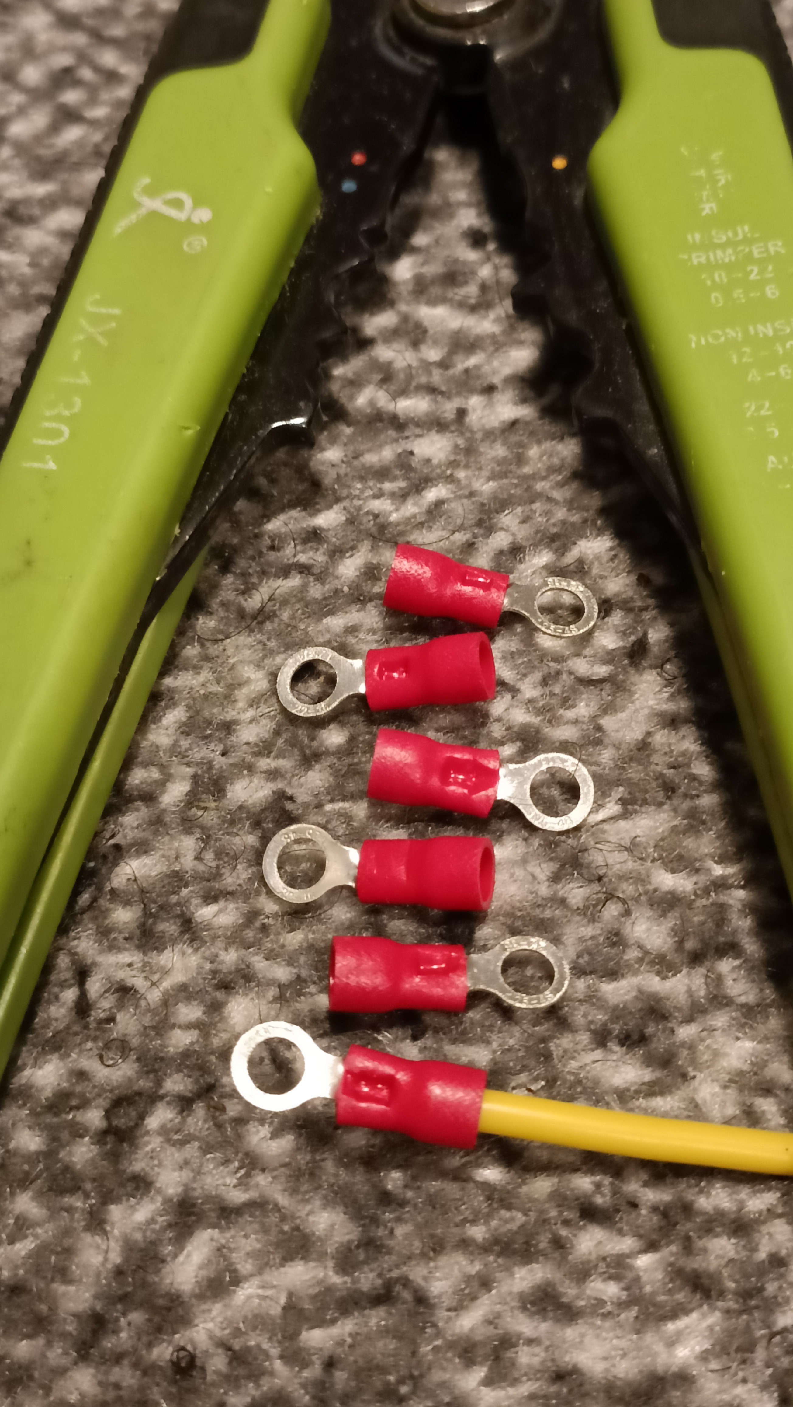
- 4.3mm ring, red (22 - 16AWG) insulated crimp
- M4 thin brass nut
- 16AWG yellow silicone wire (1 metre)
I've also got silicone bed spacers installed.
Crimping the ring onto the wire
I feel somewhat proud of myself for splurging an extra 20p on the set of 25 of these instead of 10, because it took 6 attempts to get a crimp that was sufficient:
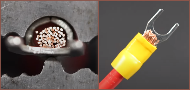
First I had looked up the tips for doing a crimp in the first place, such as crimp orientation and splice length.
I'm using the JX-1301 and I had to strip about 2mm before the minimum helper barrier (approx 5mm from the cutting pincher).
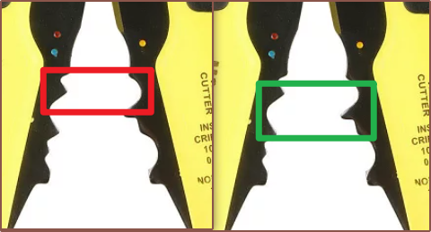
Then I tried a few times using the crimp rectangled in red, before seeing that the one in green looked like it would compress further in. The first time with the latter (5th attempt overall), I accidentally crimped at an angle but it seemed that there was potential so I tried again:
Installing the wire onto the tramming bolt
Now that I actually had a crimp termination, I could move onto installing it. I tried a few things and decided that the best solution would be to use some cutters to cut out a small (30 degree or so) portion of the top ring section of a silicone spacer:
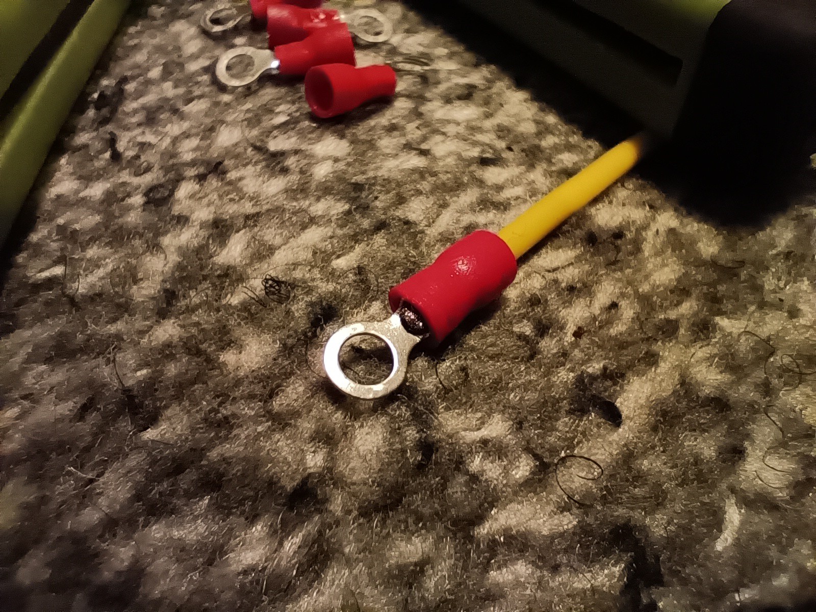
Then I lightly bent the ring termination so that it would screw on the underside of the bed flush, put the ring termination on the bolt and followed it with a thin M4 brass nut, using a 7mm spanner to tighten it. Lastly, I placed the spacer back on and it seems to have all worked as the spacer is in contact with the underside of the bed and my multimeter reads 0.0 Ohms between the bed and the other side of the yellow silicone wire.
Lastly, I've thread the wire through the sheath.
Discussions
Become a Hackaday.io Member
Create an account to leave a comment. Already have an account? Log In.