 ElectroBoy
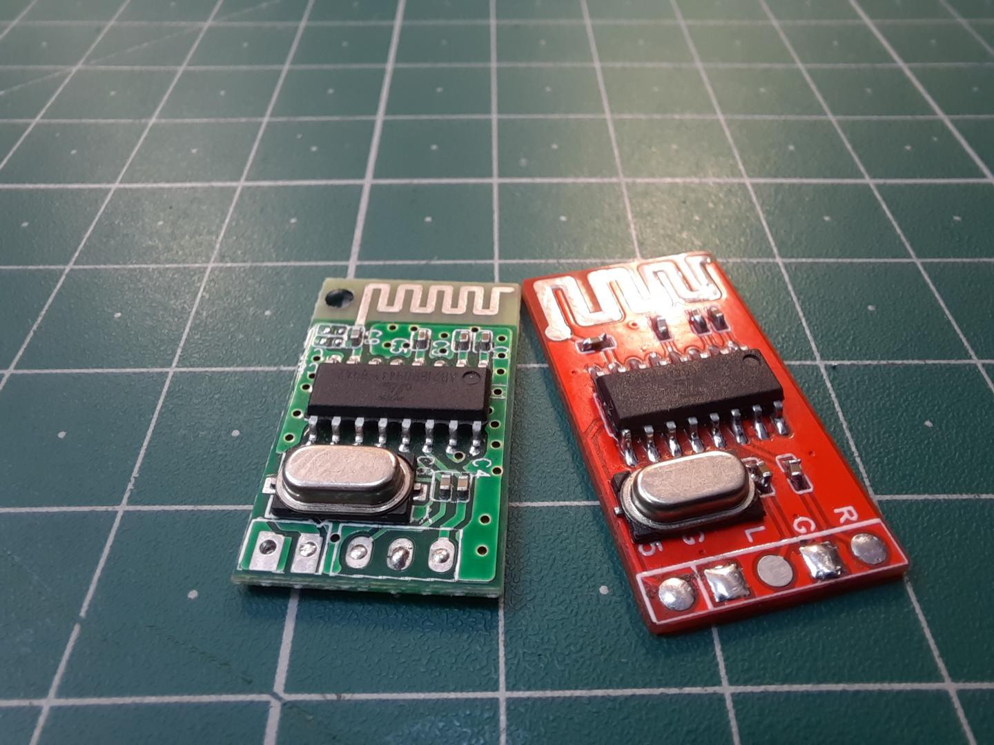
Hi guys, I am working with Bluetooth audio modules, chips and cards Since 2021. And finally, I tried to release my own version of Bluetooth module. Today’s Bluetooth chips are very chip and integrated. I got my hands on some JL series Bluetooth chips, these are made in China and doesn’t offer any kind of datasheets.
But searching a little bit more on internet, I found some circuits and IC package details. Which are similar to my version JL_AC6939B_SOP16. I cross checked all the connections through datasheet and Bluetooth module that I have. Let’s make the compatible circuit and order some of them from JLCPCB.
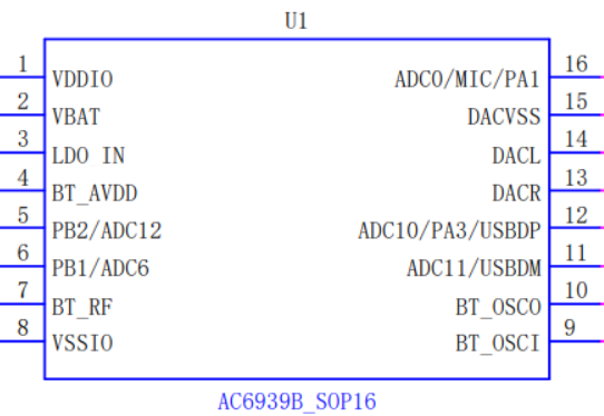
JL series Bluetooth chips (AC6939B_SOP16):
Nowadays, these are very popular, highly integrated and cheapest ICs with a lot of features. Available globally and manufactured in China, yet there is no any details or datasheets about them on web. I think manufacturer doesn’t want to disclose the info.
How I got Pinout and circuit:
After searching the specific IC number with package details, SOP 16 pin. I found a website chenbingdom.com, that may give the pin details and circuit description about this JL series ICs. This website uses a http: unsecure connection, so make sure before you reach to them. All the PDF and datasheets are in Chinese language and provide only the schematics of the circuit. Which can be modified further as per requirements.
Features of my version chip (AC6939B_SOP16):
1) Frequency range: 2402-2480 MHz
2) Modulation type: GFSK (Battery life saving technique)
3) Working voltage: 3.0 - 5.5volts
4) Low power consumption: 14mA @4volts
5) Low components used
6) Clock: 24 MHz Crystal
7) Stereo mode available
8) USB supported
9) Onboard Mic options
10) Led indicator mode available
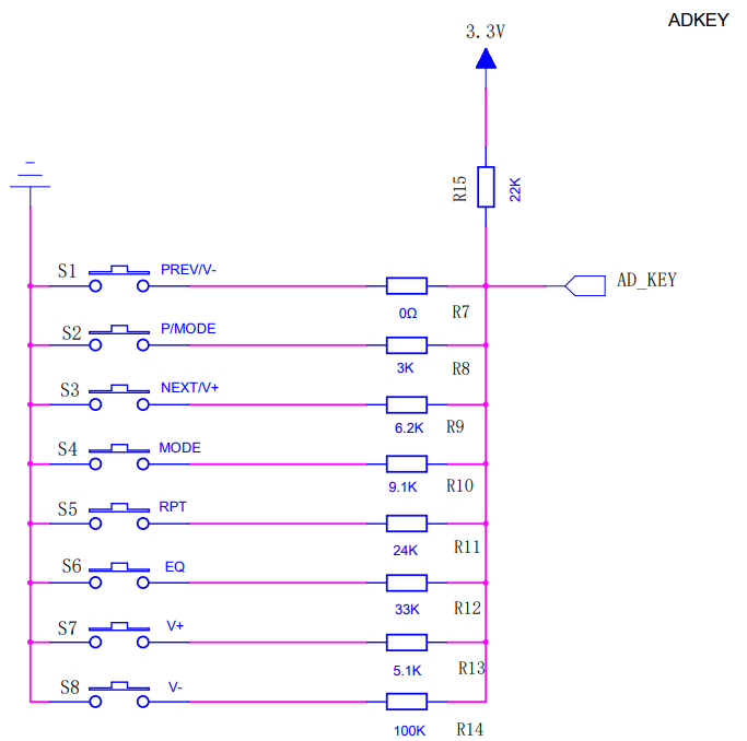
11) AD Key supported (Increase/ Decrease volume and channels)
12) 10-meter range
Circuit Diagram:
This is circuit for chip 6939B, you can get specific IC pinout and schematics from Here
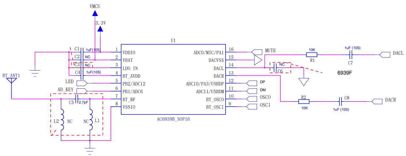
In the circuit 24MHz crystal oscillator is used without capacitors in series with it. Also, the SMD inductor is not mandatory to use. This ic supports dual channel audio out, so we can use this with stereo audio amplifier systems.
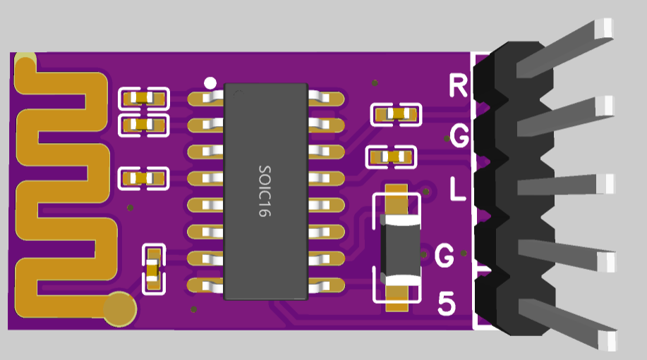
Modified circuit layout:
The real operating circuit do not need too many components, that's why I draw a simplified schematics by my own.
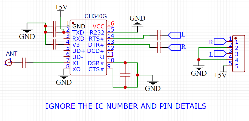
just ignore the IC pins and name. I am using ch340g in the schematics because this bluetooth IC is anonymous and package is same SOP16. You can see the Real pinout in above image from this. In case you want to modify anything you can download the Gerbers from here. If you want to use my layouts then open source link is here.
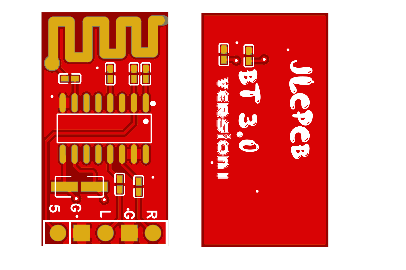
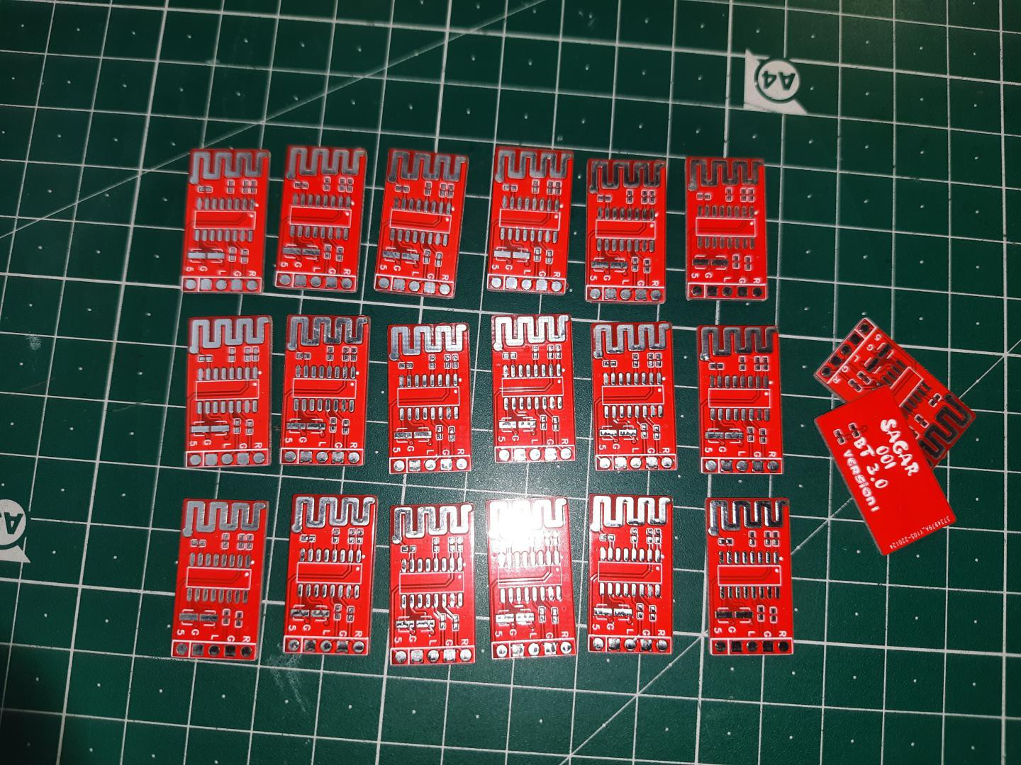
PCB layout:
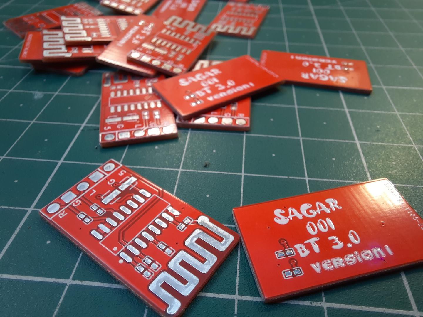
After making a cool circuit, I designed the PCB in Easyeda and Order it from JLCPCB. They are offering the PCB prototypes in cheapest. I got 30pcs of these small PCB with the thickness of 1.2mm and red color Hasl finishing just in $5. Download Gerber files from here.
And here is a special offer for you guys, Sign-up to JLCPCB using this link and get free coupons worth $27. Try their SMT assembly service to get rid of soldering and assembly process.
The ordering process is also quite simple, just follow these steps.
Go to JLCPCB> Upload Gerbers > Select quantity, color and surface finish> Add to cart > Checkout and receive package within 7 days.
Components needed:
1) AC6939B_16_SOP Bluetooth Ic
2) 24Mhz crystal
3) 100nf capacitor
4) 15 pf capacitors
5) Wires and connectors
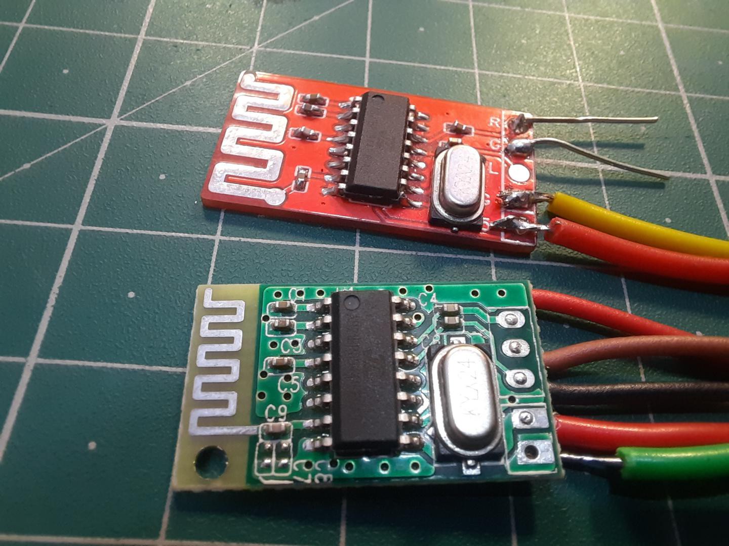
Assembly:
I got all the components from the JL group of Bluetooth chip, I can’t share the BOM officially as per their rules. Then I solder the 24Mhz crystal.
Then the main chip and some supported capacitors circuitry. All the work can be done using Hand soldering method, no need of special soldering machines.
I supplied the circuit with 5 volts and then tried to connect Bluetooth using mobile. Because this is using Bluetooth 3.0 so easy to pair with all devices except auto connect.
Checking the operation in Oscilloscope:
You can check any audio device just by giving 1Khz wave using online tone generator, this will show the reading of peak to peak volatge and quality of signal.
In case you don't have oscilloscope check Sagar's tutorial on Dual channel Arduino based Audio oscilloscope.
Pairing with mobile:
Just power on the module by giving 5v supply, then open the bluetooth terminal in your mobile and tap On bluetooth. This will scan the nearby devices, the name of by bluetooth is set to 3.0 by default. Now tap pair and the pop up show you the connection method and then pair your device with module.
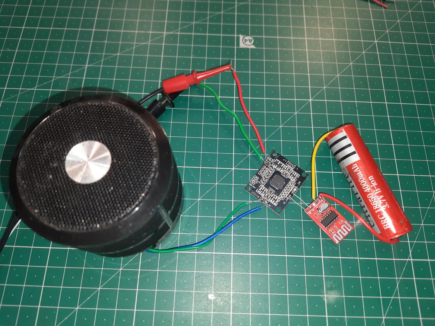
Testing with Audio amplifier:
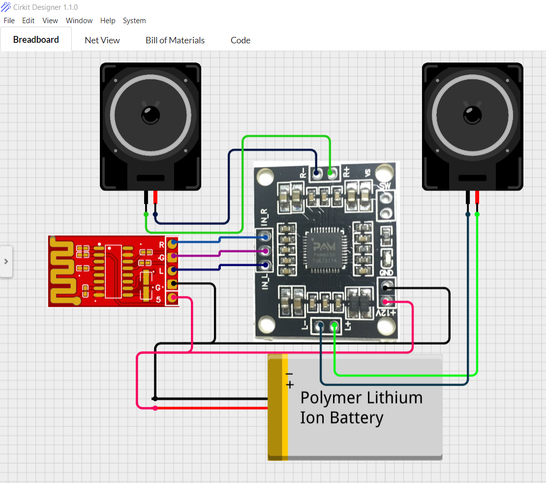
Then I paired the Bluetooth chip with a Class D amplifier to check the operation of my module. See the diagram for full wiring.A low power speaker is attached to the output end. Keep in mind if the voltage across Bluetooth IC increased from 5volts, it will damage instantly. So you can use voltage regulators(LM7805) to prevent chip burning.
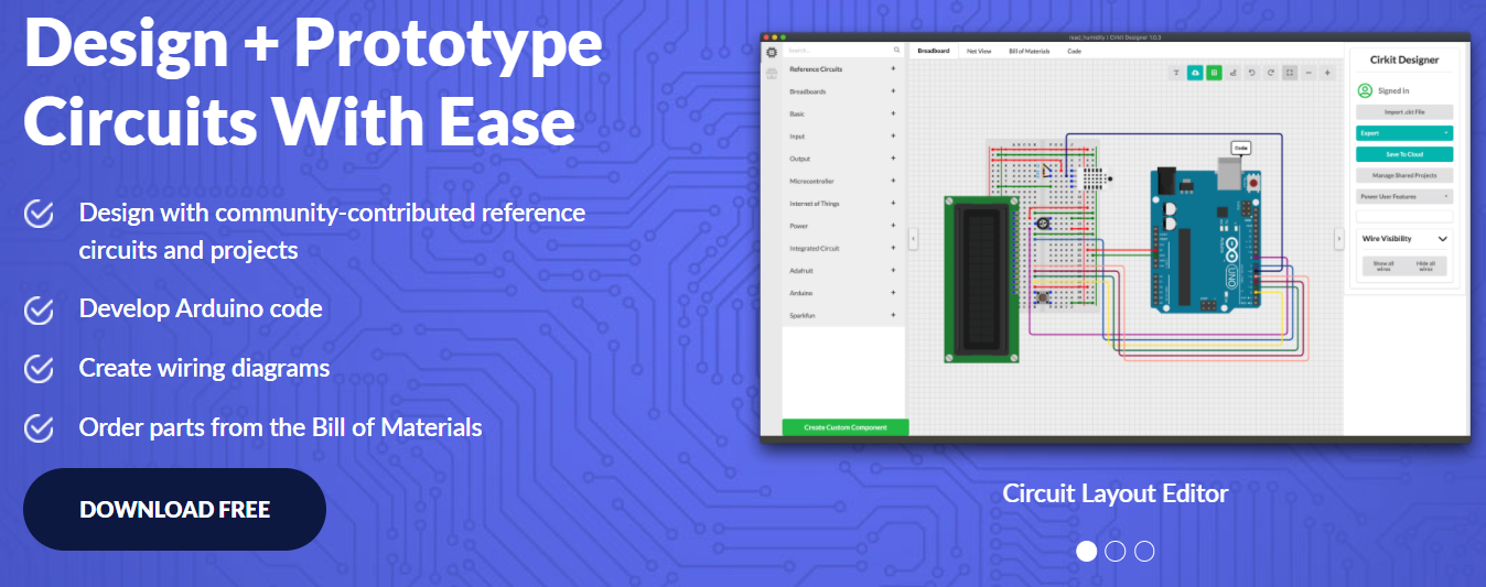
This Circuit presentation making software is really awesome named "Cirkit Designer". I always make my wire diagrams for college presentation using this, gives a clear and better look to your schematics. It also gives you the ability to view the circuit net diagram and BOM (bill of materials). This is very helpful for presenting yourself well as an electronics student or hobbyist, and the bill of materials helps to estimate project cost and procure parts.
For now this is totally free for all, You can download Cirkit designer from here.
Cirkit Designer will become the one-stop-shop to help you progress from concept to fully working breadboard prototypes. Simulation will also be added in the future, so that you can test your circuit before buying parts and building anything.
Conclusion:
This is working perfectly fine, I played a lot of songs and after testing it for an hour, I am happy. There is no any type of humming or noise in this Bluetooth also the output signal is quite decent voltage peak value. Next time I will build a Bluetooth for my Car old stereo system. Once again big thanks to JLCPCB for sponsoring this awesome project.