 hesam.moshiri
An ultrasonic range finder is a useful tool in a variety of real-life and robotic applications, such as in obstacle avoidance and distance measurement systems. The ultrasonic range finder measures the distance by emitting a 40KHz pulse of ultrasonic sound that travels through the air until it hits an object, then it measures the delay of the reflected signal and sends proper commands to other units.
I used an SRF05 ultrasonic sensor and an ATTiny85 microcontroller. The distance data is displayed on a 128*64 OLED screen, both in centimeters and inches. Also, a horizontal bar graph provides a visual estimation of the distance. The MCU code was developed using the Arduino IDE.
To design the schematic and PCB, I used Altium Designer 22 and SamacSys component libraries (Altium plugin). To get high-quality PCB boards, I sent the Gerbers to PCBWay and purchased original components using componentsearchengine.com. To examine the current consumption of the circuit, I used the Siglent SDM3045X multimeter.
Isn’t cool?! So let’s get started!
Specifications
Input Voltage: 6-24VDC
Current Consumption: 24mA
Detection Range: 2-400cm (see text)
Distance Data: Centimeters, Inches, Bar Graph
Display: 128*64-Yellow Blue OLED
Circuit Analysis
Figure 1 shows the schematic diagram of the ultrasonic range finder device. As it is clear, the circuit consists of four main parts: sensor, power supply, MCU, and display. I explain each part separately.

Figure 1
Schematic diagram of the ultrasonic range finder (Altium)
SRF05 Ultrasonic Sensor
I used an SRF05 ultrasonic module for the circuit. There are a variety of SRF05 modules in the market, I used the one that is shown in figure 2.
The quality of the modules might vary, so the maximum detection range can not be guaranteed. Some of them have blue solder-mask and some are green, also different manufacturers provide such modules.
According to the SRF05 module datasheet:” The SRF05 is an evolutionary step from the SRF04, and has been designed to increase flexibility, increase range, and to reduce costs still further. As such, the SRF05 is fully compatible with the SRF04. The range is increased from 3 meters to 4 meters. A new operating mode (tying the mode pin to the ground) allows the SRF05 to use a single pin for both trigger and echo, thereby saving valuable pins on your controller. When the mode pin is left unconnected, the SRF05 operates with separate trigger and echo pins, like the SRF04. The SRF05 includes a small delay before the echo pulse to give slower controllers such as the Basic Stamp and Picaxe time, to execute their pulse in commands.”

Figure 2
An SRF05 ultrasonic module (blue solder-mask)
Power Supply
The main component of the power supply is TS2937CW50 [1] regulator (REG1). It is a +5V SOT-223 LDO regulator. According to the TS2937 datasheet: “TS2937 of fixed-voltage monolithic micro-power voltage regulators is designed for a wide range of applications. This device excellent choice of use in battery-power applications. Furthermore, the quiescent current increases slightly at dropout, which prolongs battery life. This series of fixed-voltage regulators feature a very low ground current (200uA Typ.) and very low drop output voltage (Typ. 60mV at light load and 600mV at 500mA). This includes a tight initial tolerance of 2%, extremely good line regulation of 0.05% typ., and very low output temperature coefficient.”
FB1 and C5 reduce input voltage noises. D1 is a Blue 0805 LED to indicate a proper supply connection and R2 limits the current of D1. C4 and C6 are used to reduce the noises of the +5V supply rail. P1 is an XH-2P female connector to connect the supply wires to the board.
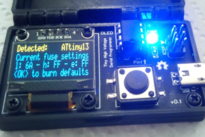
Microcontroller
IC1 is an ATTiny85 MCU [2], which is the heart of the circuit. I selected the SMD package of this chip. According to the Tiny85 datasheet: “The ATtiny25/45/85 provides the following features:...
Read more »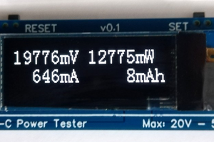
 sandy
sandy
 Mrinnovative
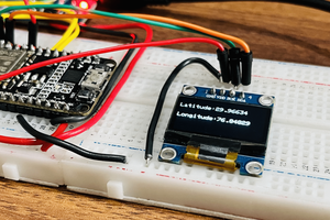
 Sagar 001