Low-poly design is a style which can be applied to three-dimensional models. It intentionally reduces the number of polygons, which make up the mesh of the model. Because that obfuscates some details, it is kind of a minimalistic style – and I love it. So I wanted to apply it to my keyboard case.
But simply taking my case from Fusion 360 (which is essentially a box), converting is to a mesh and reducing the number of polygons wasn't going to work. Because all the corners and edges would just disappear. Below I describe my steps to a successful low-poly design using Fusion 360 and Blender.
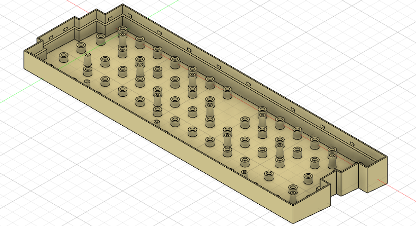
Step 1: Model a Basic Case in Fusion 360
Based on my keyboard plate, I created a basic case. This already includes an angle of inclination of 5 degrees.
Step 2: Create an Expanded Form using Form Mode
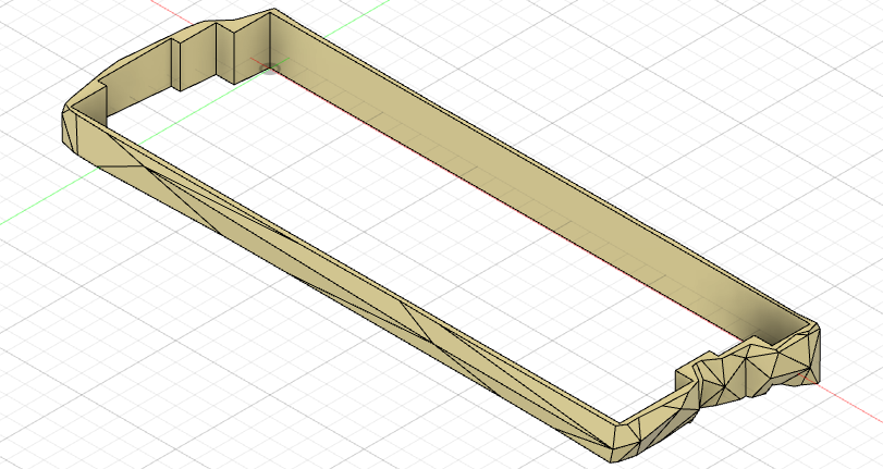
In Fusion 360, I created a new Form and, to start off, inserted a box which roughly enclosed the existing case body. The form should reflect a certain number of details of the basic case, such as the stepped edges on the left and right side. I inserted additional edges and pulled them around using the Modify tool until I got something like this:
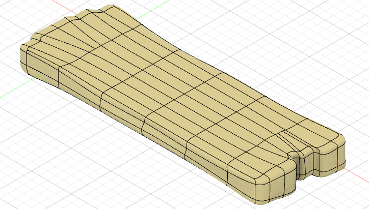
You can see that I thickened the form on either end to ensure that there are still some edges left after I applied the low-poly style. I also introduced some irregularities along the long sides of the case. That is because I wanted the low-poly pattern on the front and back side as well. Without those dips and humps, the side would have just be flattened to a single polygon.
Step 3: Convert Body to Mesh and Reduce
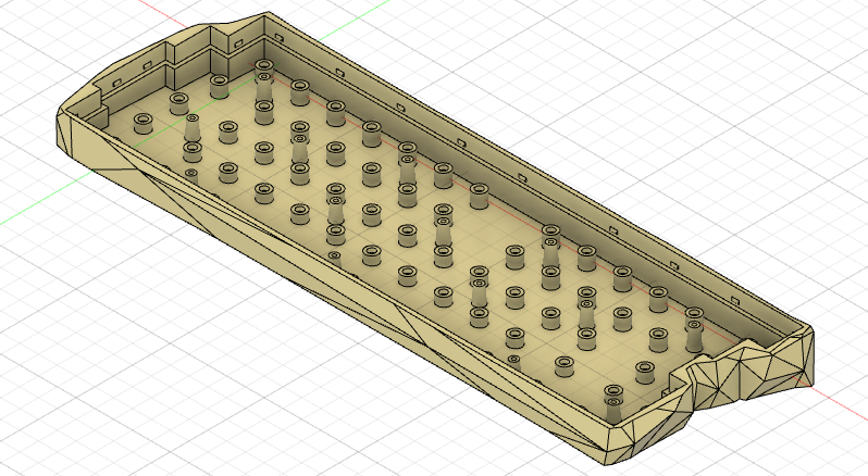
In Fusion's Mesh tab, the Tessellate command converts a regular body into a mesh. I then ran the Reduce command with the following parameters.
- Type: Proportion
- Remesh Type: Proportional
- Proportion: 0.3
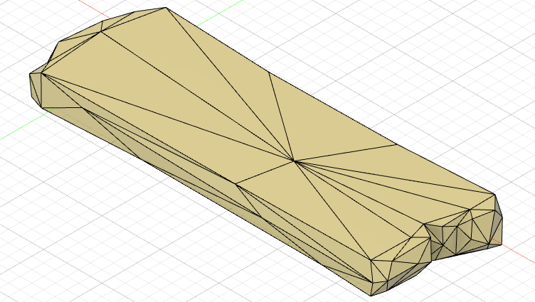
The result was very much to my liking. However, there was one corner that was cut off too much. meaning that there would not have been a continuous upper edge on the case. Getting those fine details right in Fusion 360 is hard, because you never know how the reduced mesh will look like when making modifications to the initial form from Step 2. Believe me – I dragged the points and edges all over the place without success.
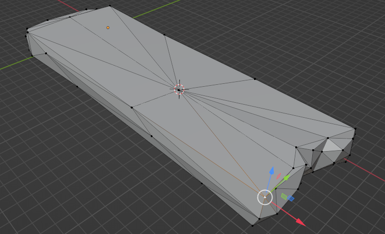
Step 4: Directly Modify the Mesh in Blender
Instead of hoping that changes to the form lead to an improvement in the reduced mesh, I decided to work directly on the reduced mesh and make the changes there. Blender was, weirdly enough, the only tool I found which allow individual mesh vertices to be repositioned. I used the STL file format to transfer the mesh from Fusion 360 to Blender and back.
In Fusion 360, I used the Insert Mesh command to import the edited mesh. Some iterations were needed between this step and the next ones to get it right.
Step 5: Cut-off Unnecessary Material
To replace the four sides of the original case from Step 1 with the new design, I first converted the mesh to a solid body. Then I applied the following operations:
- From the original case, cut away all the corners which are sticking out from the low-poly case (Combine Tool: Target Body is original case, Tool Bodies are all the protruding corners of the original case, Operation is cut).
- Hollow out the low-poly body, so only the four outer faces are left (Extrude Tool: Profiles is the plate sketch, Distance such that it cuts all the way through top and bottom, Operation is cut).
- Cut off the low-poly body at the top and bottom, such that it is flush with the top and bottom of the original case (Split Tool: Splitting Tool is the top/bottom surface of the original case, Extend Splitting Tools; Remove Tool on the cut offs)
Step 6: Combine Low-Poly Surface with Case
Finally, I joined the low-poly body with the original case using the Combine Tool.
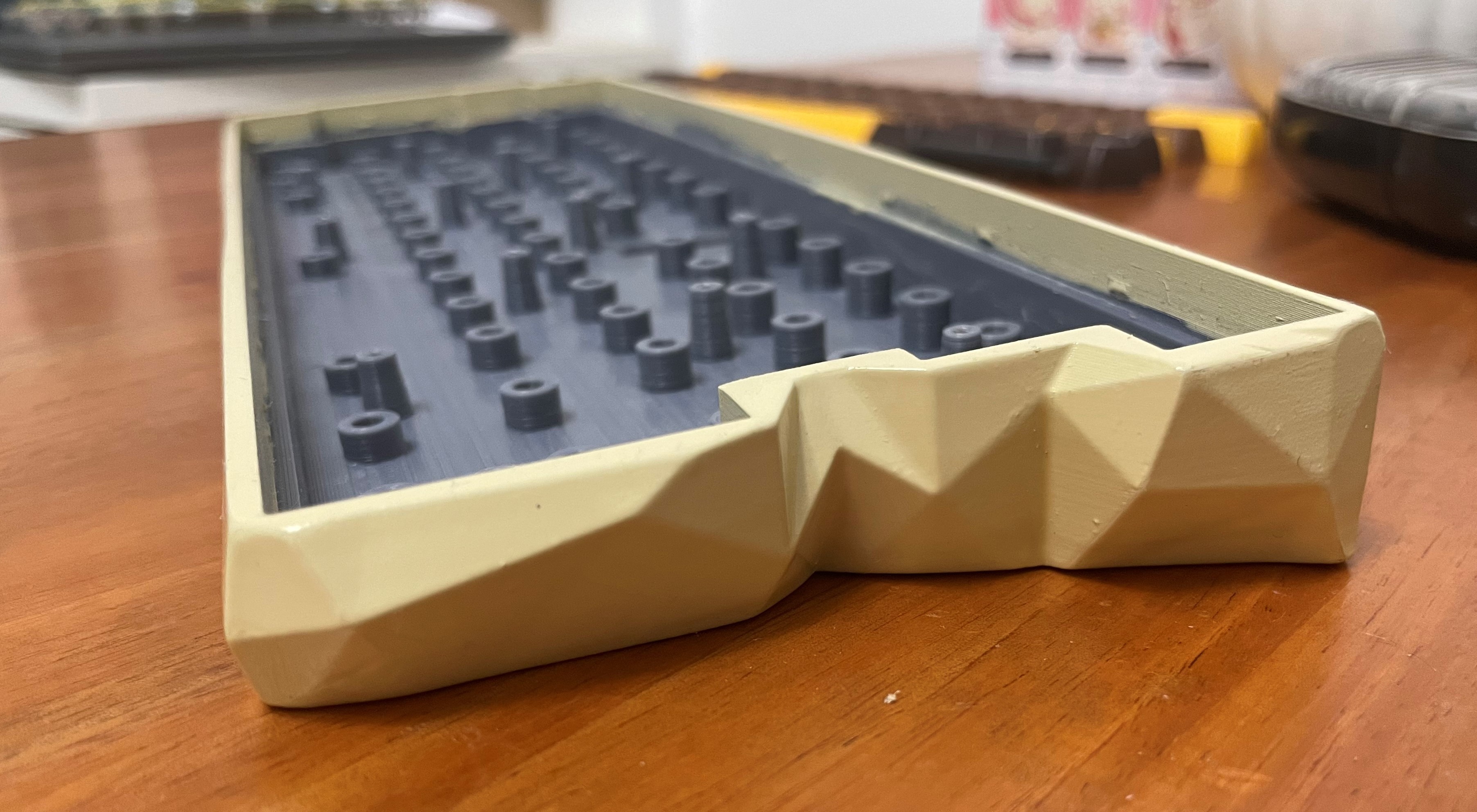
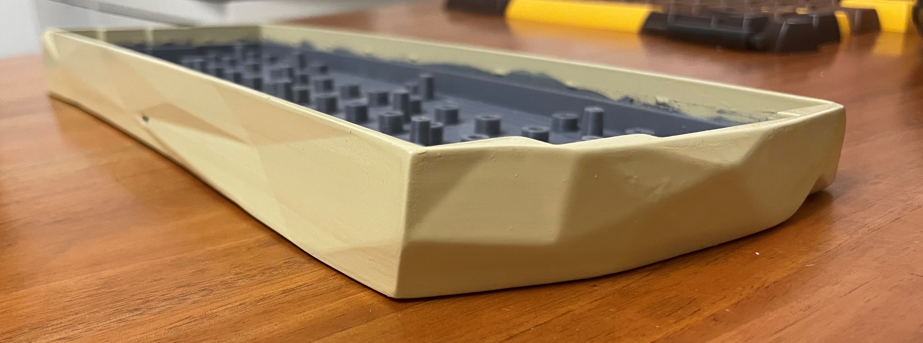
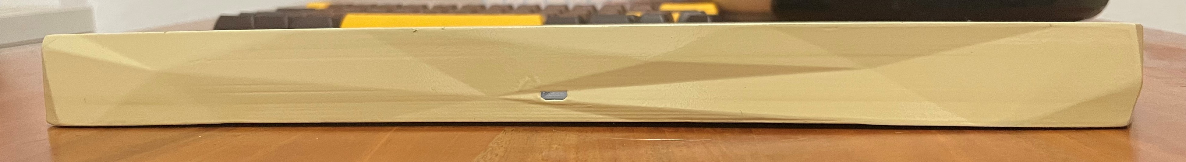
I uploaded the final case to this project for you to print. It can also be found in the Github repository along with the firmware files. Here are some pictures of the final result:

Discussions
Become a Hackaday.io Member
Create an account to leave a comment. Already have an account? Log In.