 DeepSOIC
We all know Ohm's law is not really a law. It's just a definition of the term "resistance", and a statement that for many things, mostly for things made of metal, the electric current is proportional to applied voltage for some range of voltage/current.
I assumed it should hold pretty good for copper conductors.. Sooo wrong!
I wound a coil. Measured its inductance and DC resistance.
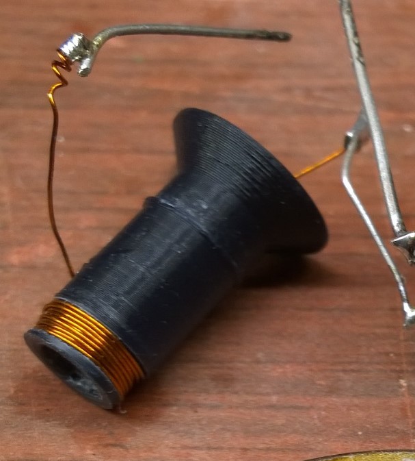
Inductance is 15 uH. R = 0.2 Ohms. Number of turns = 35, wire diameter 0.33 mm.
Then, I estimated the amount of current it should take to achieve a magnetic field of about 1-2 teslas inside. 300 A. So, all I need is a voltage of 60 V. Too easy....
So I dug out a photo flash capacitor (150 uF 300 V electrolytic). Charged it up to 100 V... Boom! and, nothing. No effect on the magnet.
-----
Why?
I hooked an oscilloscope across the capacitor, to see that it took more than 50 us for the capacitor to discharge. That means the discharge current is only about 80 A. That's more than 3 times less than I expected.
I was afraid that the internal resistance of the capacitor can be a problem. But from the oscilloscope trace, it was clear that the resistance is actually in the coil. WTF?
Skin effect maybe? 50 us -> kinda 20kHz frequency. Looking up skin depth on Wikipedia -> about 0.5 mm. The wire radius is only 0.15 mm, so skin effect should only slightly affect the process, not dominate it.
So what's the deal? Is it maybe proximity effect? or maybe something else? Or maybe inductance of the coil kicks in when I didn't expect it to kick in? Post your ideas!
-----
I upgraded the capacitor to 820 uF, and it looks like now I finally get something around 300 A. And, it does magnetize the ball magnet quite a bit more than I could achieve by using other neo magnets, so I'm on the right track. I will inscrease the energy further, and hope the coil won't explode on me as it happened to Mike, when he was testing a circuit breaker with destruct-o-tron.
Discussions
Become a Hackaday.io Member
Create an account to leave a comment. Already have an account? Log In.
I have a hunch about why the Ohm's law looks faulty in your setup.
Can you please put some detailed pictures of your setup during a measurement? I mean _real_ pictures during a _real_ measurement, not just a cosmetic arrangement of the parts for a photo shoot. I am asking this because sometimes the direction of the probe (the orientation in space, even when the electrical connection points remains the same) does matter. A picture where the scope, the probe and the rest of the components are in the same frame will be great.
A few weeks ago I made a setup where 2 probes connected at the same points were showing different voltages just because the probes have had different orientation in space. As a hint, I was trying to test professor Walter Lewin's claim that the Ohm's law does not stand in non conservative fields.
LATER EDIT:
When I said "not just a cosmetic arrangement" I was not talking about the closeup already published. I was saying that because, if someone would have asked me what I just asked from you, I would probably redo an approximation of the original setup, with the same topology but without powering it.
Are you sure? yes | no
I guess you commented the wrong project log.
The photo where I show how I probe the pulse is the real thing. I should probably make a video of acquiring the pulse, then.
Are you sure? yes | no
Wrong guess. Relative position between EM field, probe, probe's cable and scope does matter. In the gallery I could not find any picture with all of these in the same view. I can see only a closeup where I need to guess how all the setup was connected. Does your waveform and peak values varies with probe orientation?
I'm not sure if a video will help more then a complete picture, as you wish.
Anyway, if you already found the explanation for the measured values, then don't waste your time with this. I already have enough contradictory results from my own experiment.
:o)
Are you sure? yes | no
Maybe it's connected to self-induction of coil?
Just read on wiki: https://en.wikipedia.org/wiki/RLC_circuit.
Are you sure? yes | no
Well, now I think it actually is the case!
First, I measured the actual waveforms. At first glance, they look all right.
Second, my quick estimate of current wasn't accurate at all. See the waveforms.
Third, I made a foolish mistake during estimates, and forgot to look at the spreadsheet I was using carefully. The energy that is stored in magnetic field of the coil at current of 300 A is 0.68 J, which is just a bit lower than the energy in capacitor, 0.75J. I was under impression the energy in capacitor was way higher, which made me assume inductance effects should be small, while they are not small at all. So it kinda all makes sense now.
Are you sure? yes | no