 gianlucag
The program is written in assembler in order to squeeze as much as possible into the available 1kB program memory. The code is composed of two main section, the idle routine loop and the ISR routine which get triggered when a music beat is detected.
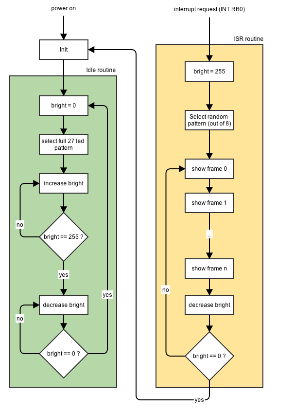
The idle routine makes the cube glows until a music beat is detected by the hardware. At that point, the interrupt is triggered and the ISR routine get. called. The ISR picks one of 8 possible animation at random and starts displaying it, frame by frame. Each frame of an animation is encoded using 27bits (1 bit for each of the available 27 leds). Each animation is composed of many frames. A frame is shown by turning on or off the leds as the 27bits frame dictates. Each led is lit by addressing its column (there are 9 columns in a 3x3x3 cube) and its layer (3 layers). The animation is repeated over and over until a new beat is detected or a timeout is reached. In the latter case the cube goes back to idle mode.
Here it is the complete schematic. The PIC 16F84 is on its classic configuration: a reset circuitry, oscillator section and output GPIOs. The reset section is made of a switch button, current limiting resistor (R2) and pull-up resistor (R1). The oscillator is a simple 4MHz quartz with two 10pF capacitors.
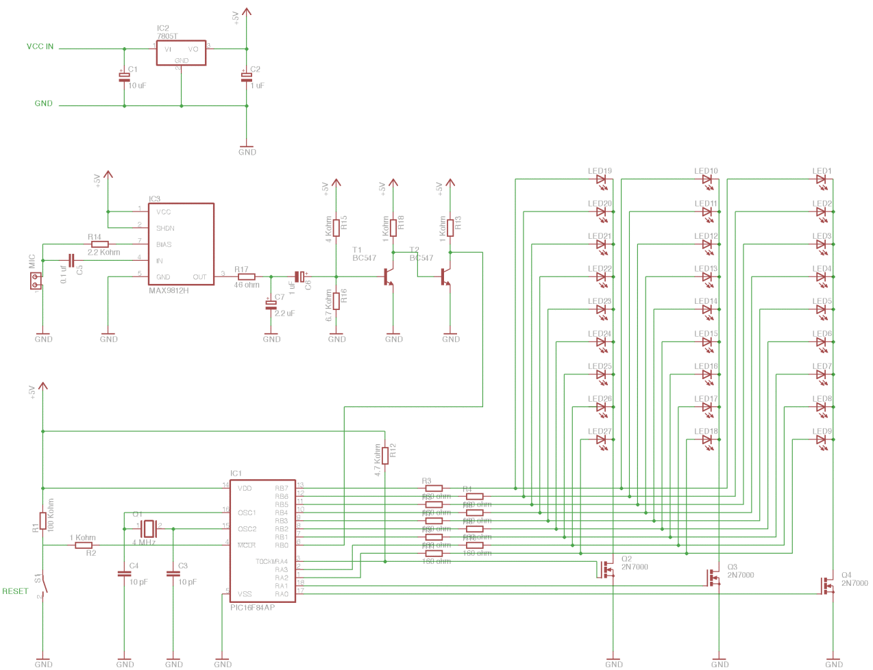
GPIOs RB1-RB7 (PORTB) and RA2,RA3 (PORTA) drive the LED bus (9 lines). GPIOs RA0,RA1 and RA4 select respectively the bottom, middle and upper LED layer. Note that RA4 is an open-drain GPIO when in output mode so a 4.7 Kohm pull-up resistor is required; the other GPIOs don’t require such resistor.
The actual beat detection is done by three main parts:
- MAX9812H linear amplifier (IC3)
- RC low-pass filter (R17, C7)
- Signal squarer (T1,T2)
The square wave signal is directly fed to RB0 which is programmatically set as interrupt pin. On each signal pulse (i.e. music beat) the LED Cube selects and shows a different LED pattern.
 Michael Möller
 ClockLoop
 Stefan Kratz