The process involves removing the A4988 IC from the board (either by severing the connection closest to the chip or using hot air to lift the chip off) and then tapping off of the logical voltage connections on the board (refer to the picture below)
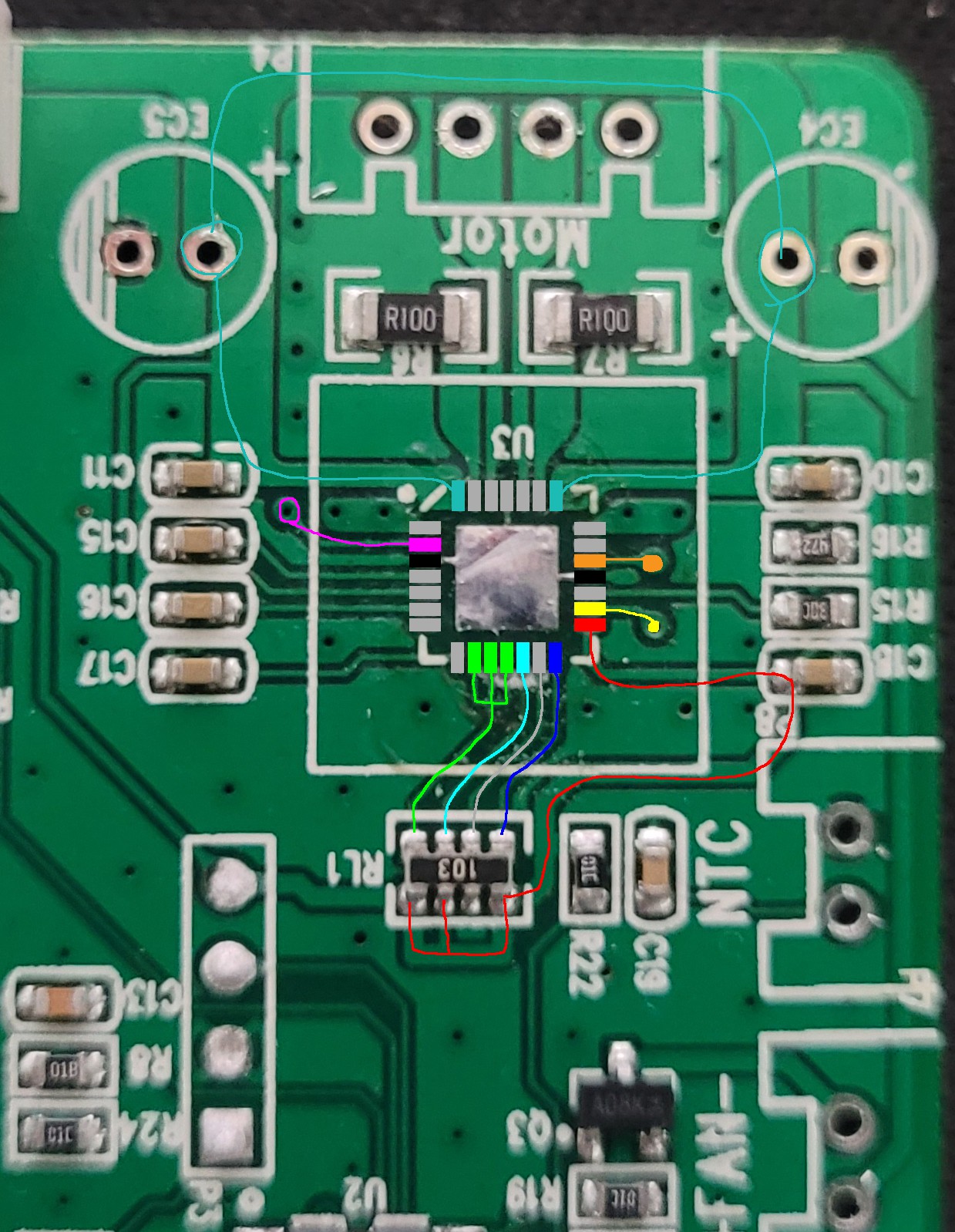
Red is the 5V logic voltage that should never be connected to 12V (DO NOT tie this to the 12V rail. This will fry everything on the board.)
Orange is the direction, yellow is the step signal, magenta is the Enable pin, teal is the 12V motor power connection and green is the microstepping configuration (which in this case is just set to 1/16 step mode)
Both Reset and Sleep pins are disabled through the resistor.
Strangely, both NTC and fan connections are present but never utilized.
While you're at it, you might want to tape the buzzer so it's quieter.
Modification:
1. Remove the A4988 chip. We are not going back so you can even mill it off if you don't have a hot-air station.
2. Acquire AT2100 stepper motor driver module. It is essentially A4988 with bits of TMC2100 mixed in.
3. Either using a StepStick Protector module (like I did) or with a small circuit board, connect the module as shown below.
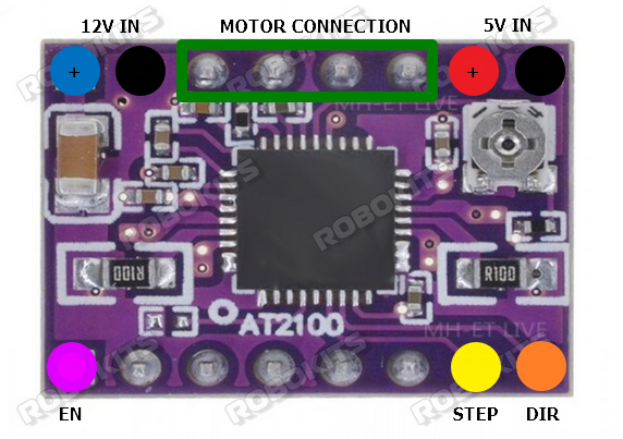
4. Set the motor current to around 700mA.
5. Button the unit back up. If you want, you can solder the JST connector you salvaged from the board where it is marked for ease of maintenance.
6. If everything went well, the unit should perform identically with reduced noise level when running in Wash mode.
Note: It is recommended to add 470uF/1000uF electrolytic capacitor to the 12V input.
 Torbjörn Lindholm
 John Taylor
 Taylor Schweizer
 David Brown