In many homes, accidents with cooking gas occur because people forget to close the valve. The gas leaks and can generate two major accidents: explosion or death by aspiration in large quantities during sleep.
One of the ways to avoid this is through a gas presence monitoring system. This is done through the use of sensors.
In this article we will build a system to monitor the presence of cooking gas. We will develop an electronic control board and an enclosure to store the circuit structure. See some images of this project.

The 3D enclosure design was developed with JLC3D. The entire structure was designed to be manufactured with the resin material to obtain a better finish and surface quality of the structure.
This enclosure costs approximately $6.50. However, JLC3D offers a $5 discount coupon for you to print this or another project. Use the JLC3D coupon and receive the 3D enclosure in your home.
Download all project files through this link.
Below we will explain the complete development of the project.
Flammable Gas and Smoke monitor development
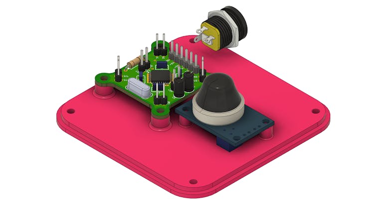
The following structure represents the electronics that were the gas sensor:
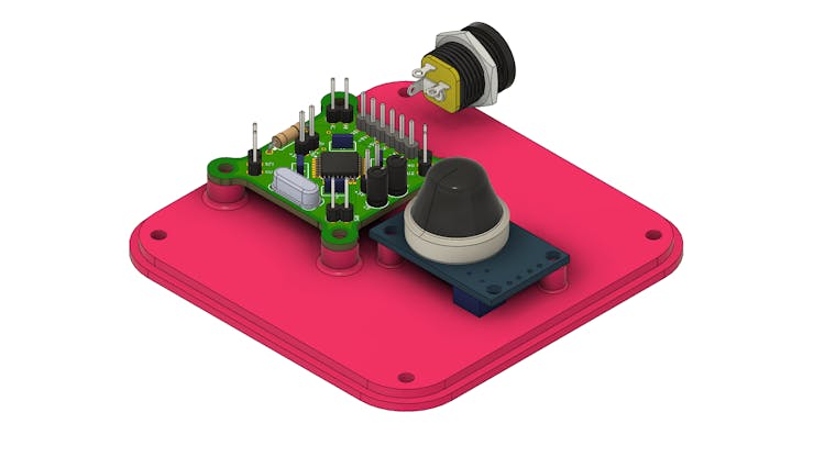
As you can see, you will use 4 electronic elements:
- Control board with ATMEGA328P-AU CHIP;
- MQ-2 Gas Sensor;
- Female Jack connector for 9V power supply;
- Enclosure.
The project is divided into two parts: the electronic structure and the enclosure. Next, we will see the operation of the electronic circuit.
Project Electronic Circuit
We developed an electronic board with an ATMEGA328P-AU CHIP. This circuit was developed to facilitate development and testing for several prototypes that use few digital inputs and outputs and occupy a small space. Below we have the structure of the electronic board.
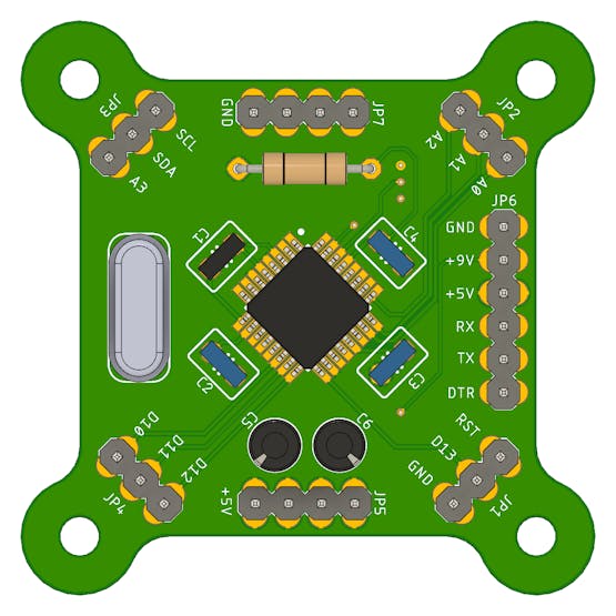
The electronic board has pins for in-circuit recording (+5V, GND, TX, RX and DTR). In addition to them, we put access to other digital and I2C pins. The latter allow, for example, the use of an LCD with I2C.
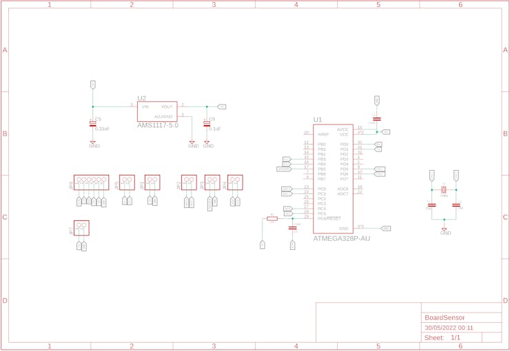
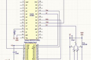
Below we have the complete schematic of the electronic circuit.
The electronic design of this board is available for download. You can download and win 5 free JLCPCB units. To do this, just follow the steps below.
- Access this link and create an account on the JLCPCB website;
- Upload the Gerbers files on this website;
- Apply the JLC-REBE coupon on the payment page to get 5 free units.
- This video explains the step-by-step process for ordering electronic boards.
The board with the ATMEGA328P is designed to receive the connection of the MQ-2 sensor and the buzzer.
The MQ-2 sensor is responsible for reading the environment and detecting possible particles of butane gas. This sensor is powered with 5V and has two forms of signals: one analog and one digital.
See its structure in the figure below.
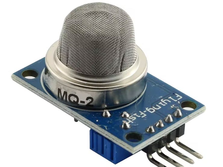
The sensor is installed in the internal structure of the enclosure.
In addition to the sensor and the electronic board, we have a Jack connector to facilitate powering the internal circuit.
Next, we have the enclosure structure developed for the project.
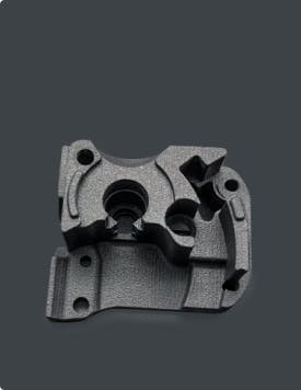
3D Development of the Project Enclosure
Enclosure was developed to facilitate the installation of the electronic circuit and to better present the quality of the prototype.
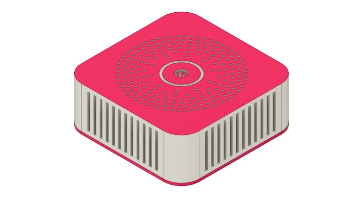
The prototype structure was developed with several holes in the upper region and cuts in the lateral regions. This facilitates the entry of gas into the sensor region.
The enclosure structure is divided into two parts: top cover and base.
Below is the base figure.
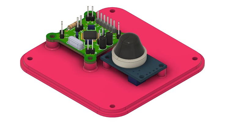
It has all the holes for fixing the electronic control board and the sensor. In addition to the fixing holes for the plates, we have 4 holes at the ends fixing the base with the cover. See the figure below.
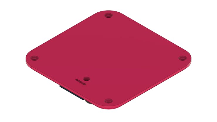
The base frame has a fifth hole to allow the user to adjust the sensitivity of the sensor.
Finally, we have the enclosure lid. As already mentioned, its structure has several cuts to facilitate the entry of gas into the internal region...
Read more »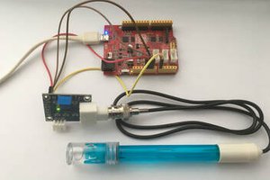
 kimbomc
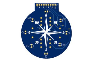
 Silícios Lab
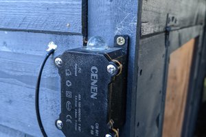
I do believe this is an excellent website. I stumbledupon it I may revisit once again since I saved as a favorite it. https://www.mymorri.net/