Intro
Our group had a 10-week period to create Dum-E, so we had to be clear on what was important to the project in order to finish the project in this time. Dum-E’s software side consisted of setting up a web server, creating an appealing user interface, and implementing a detection algorithm on the server side. Dum-E’s hardware side consisted of implementing proper motor control logic, picking out proper components so that all the electronics could be run off one power supply, and creating a PCB to organize these electronics in a neat and compact manner. Dum-E also consists of a custom pan-tilt enclosure in order to fit the chosen electronics and provide satisfactory camera placement.
One of the main goals we had in mind when coming up with an idea for this project is doing something that both spans multiple disciplines and aligns with today’s technological trend. For example, we wanted to incorporate some degree of advanced data processing, whether that be machine learning or computer vision. Building on top of the server requirements, we wanted to explore wireless architecture employed in today’s industries.
Ultimately, this led to this project, which seems to meet the aforementioned requirements and is also doable in 10 weeks. The project would incorporate some degree of automation and computer vision, has a good degree of interactions with the physical world (through the use of cameras and motors), and also require some understanding of network protocols to support multiple video streams.
While building a fully functioning product is ideally what we hope to achieve by the end of this quarter, the biggest takeaway we hope to gain from this project is understanding the technical details and design process involved in building these electronic embedded systems, such as networking, software principals, hardware designs, and electronics.
System Overview
Our system can be broken up into three major areas: (1) software, (2) electrical hardware, and (3) 3D-printed enclosure. The core logic and flow of our system are best characterized by the block diagram shown in Figure A below.
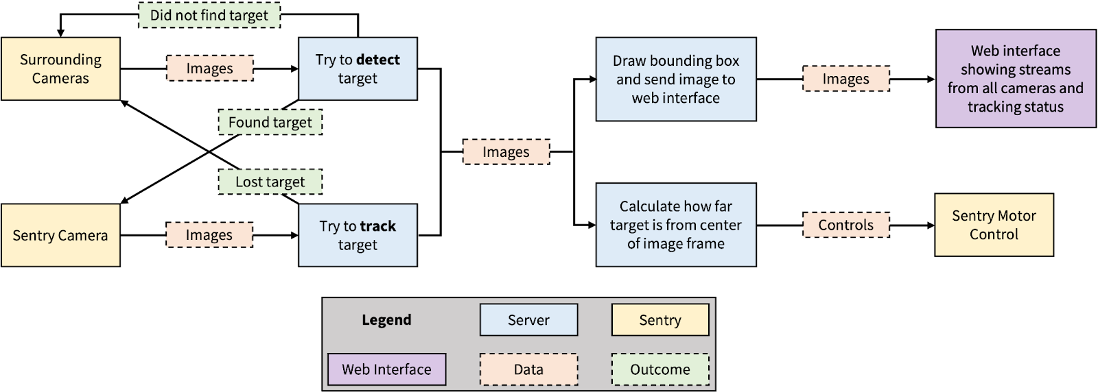
Figure A: Block Diagram
The specifics of the listed areas and parts are further elaborated in the following sections.
Software
The software can be further divided into three categories: (1) the central server and (2) the Arduino programs that run on the edge devices, and (3) the web interface. The interaction between these categories is shown in Figure B. The central server corresponds to device 2, edge devices (specifically ESP-32s) to device 3 and 4, and the web interface to device 1. The green arrows represent the flow of data between devices.
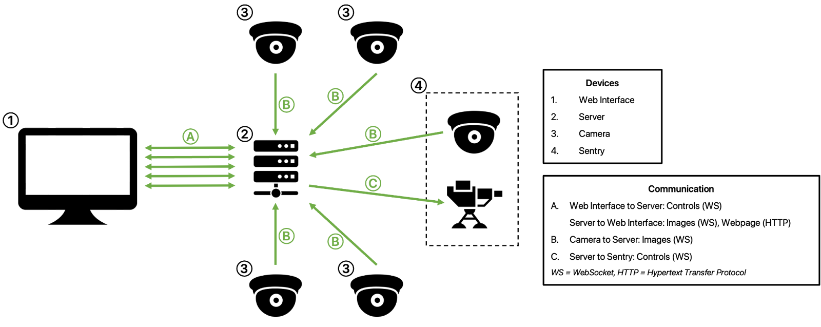
Figure B: Software Architecture
Central Server
The sentry can operate in two modes, automatic and manual, both of which can be set through a web interface. In manual mode, the user can control the sentry directly through the web interface, which continuously streams a live-feed from the sentry. In automatic mode, the sentry can be configured to track people or objects.
The central server makes up the blue blocks in Figure A and is the brain of the whole system. All processing—such as image compression, object detection, sentry control—are done on the Python server. As shown in the block diagram and the software architecture above, the server has two main responsibilities: handling the networking details and processing the images. The server is hosted using the Tornado framework and image processing is performed using OpenCV.
Network
Communication between all devices is done through the Tornado framework. The connections between each device can be characterized by the following: (1) the web interface is served via HTTP, (2) the Python server receives live images from all cameras via WebSockets, (3) the web interface sends movement commands to the Python server via WebSocket, and (4) these commands are then forwarded onto the sentry via WebSocket as well.
Note that each livestream uses two WebSocket connections, one for sending an image from the camera to the server, and another for sending that same image from the server to the web interface. Since our system uses six ESP-32s—five for sending livestreams, and one for receiving controls and controlling the motors—the system has 11 WebSocket connections opened simultaneously.
Five different connections are used to connect to the web interface instead of using just one to avoid having to do any processing on the frontend side. If only one connection were used, each WebSocket packet would need to encode additional data to indicate from which camera the packet came from. This increases the complexity of the frontend code.
Image Processing
The image processing logic is best characterized by the finite-state machine shown in Figure C. When the system first starts, it is in scanning mode. The goal of this state is to determine the general direction of where the target is. In this state, image processing will be performed on the streams sent by the surrounding cameras. More specifically, the Haar cascade algorithm is used to detect human faces. When a target is detected, the following steps are performed: (1) the camera that captured the target is identified; (2) a command is sent to the sentry instructing it to turn to the direction the identified camera is pointing in; and (3) we transition to detection mode.

Figure C: FSM for Image Processing
In detection mode, the sentry does image detection using the Haar cascade algorithm once more. If the target is found, we move onto tracking mode. If not, we transition back into scanning mode and start performing image processing on the surrounding cameras again.
In tracking mode, we use the KCF tracking algorithm to track the detected target. This is chosen, as opposed to constantly performing detection, because it is much cheaper and faster to compute. All that is needed by the KCF tracking algorithm is the initial bounding box of the target, which is given to the algorithm by the Haar cascade algorithm. If the sentry ever loses track of the target for more than 40 frames, it immediately gives up control and we transition back to scanning mode.
Arduino Edge Devices
The “edge” devices here refer to all the ESP-32s used. There are six of them used in total, five of which are the ESP-32 CAMs and one normal ESP-32. Four of the CAMs are used for capturing the sentry’s surroundings and the other used by the main sentry to track the target. The normal ESP-32 is used to interface with the motor drivers, which then control two brushless motors connected to the pan-tilt frame. All six devices also act as a WebSocket client, which is necessary for sending and receiving data to and from the central server.
The cameras used in the system take JPEG images that are 640 pixels wide and 480 pixels tall. Initially, the ESP-32 CAMs were configured to capture raw images but this drastically slowed down the microcontroller. As a result, we went with JPEG images and decoded it back into raw images on the server side using OpenCV. After testing different configurations, we are able to achieve a frame rate of roughly 20 fps across all five streams. Parameters we tuned include frame size, JPEG quality, and image format.
Motor Control Code
The normal ESP-32 receives control commands from the central server. The controls fall into one of two categories: general direction or the amount to turn in a specific direction. In scanning mode, the general direction—specifically NORTH, EAST, SOUTH, and WEST—is sent to the sentry based on which of the four cameras captured the target. Upon receiving these commands, the sentry turned to a predetermined position. The second type of commands (the amount to turn—which is determined by the difference between the target’s position and the center of the camera frame—is sent to the sentry) is determined by the difference between the target’s position in the image and the center of the image.
The motor control code is a feedback system inputting commands from the server, and inputting the state of the hardware from encoders in the DC-motors. We are only able to give direction and speed to the motors, so the encoders provide feedback on the position of motors. The encoders tick about 445 times per revolution, which lets us translate into degrees. From this the overall structure of the code is a class that stores all these values: motor position, motor desired position, previous input, and new input.
The class is in charge of all movement and deciphering for a given input. We have a function deciphering a string of relative positions from the direction the camera is facing in the following format: “tilt,pan”. If this string is different from the previous given input, then it gets deciphered and stored as encoder ticks the motor has to move, with negative numbers being the opposite direction. The class is then in charge of independently calculating the fastest direction, clockwise or counterclockwise. The code will then attempt to move the motors to the desired position until a new input is given.
The moving the motors code and updating the direction code run in parallel. This way, the motor does not have to go the full way to the requested position, and that position can instead be overwritten. We accomplish this using RTOS. On the main loop we are constantly updating the new command for the class. We placed the moving motors code into RTOS as seen in Figure D.

Figure D: RTOS code
Electrical Hardware
The hardware’s goal was to effectively drive the motors and be able to safely read the outputs of the encoders on the motors. This was accomplished by mainly using:
- 1 ESP32
- 2 DC Brushed encoder motors
- 2 A4990 Dual Motor Driver
- 1 KeeYees 5V to 3.3V logic level shifters
The ESP32 is used to connect to the server and receive inputs from the camera and generate outputs for the motors. The ESP generates PWM signals for each using two lines, one stays low depending on the direction of the motor, and the other changes its duty cycle depending on the requested velocity for the motor.
However, the ESP is not able to output enough current or high enough voltage to actually turn the motors. The motors run on 12V and are able to draw up to 0.7A each. Therefore we used motor drivers. The A4990 motor driver allows for up to two motors to be powered from one module, but unfortunately the output logic is complicated, and we were not able to catch it in time, so we ended up using two motor drivers. The motor drivers have H-Bridges that protect from backwards current from burning the DC-Motor. This simplifies any potential code as except under intense load, the motors do not have to fully stop or manually slow down to turn the other direction.
The motors also have encoders. They are basically hall effect sensors that click about 445 times per revolution. This allows for a feedback system in which the ESP know where the motors are relative to their starting position. Each encoder requires two pins, which drives one of the lines high when it ticks while keeping the other line low. Which line is always low determines which direction the motor is spinning, clockwise or counterclockwise. However, these encoders input and output 5V, which is dangerously close to the upper limit ESP pins can input, so to stay safe, we are using logic level shifters from 3.3V to 5V to interact between the ESP and the encoders.
PCB
In order to reduce wiring, we made a PCB. This PCB was designed to input 12V and be able to power all the previously mentioned systems, as well as all the 5 cameras in Dum-E. Since the ESP-CAMs, ESP32, encoders, and logic level shifter all work on 5V we needed to step down 12V. We used a DC-DC 12V to 5V converter to step down, along with two 10uF capacitors that were recommended in the data sheet to smooth out the input and output and prevent the CAMs and ESP32 from brownout.
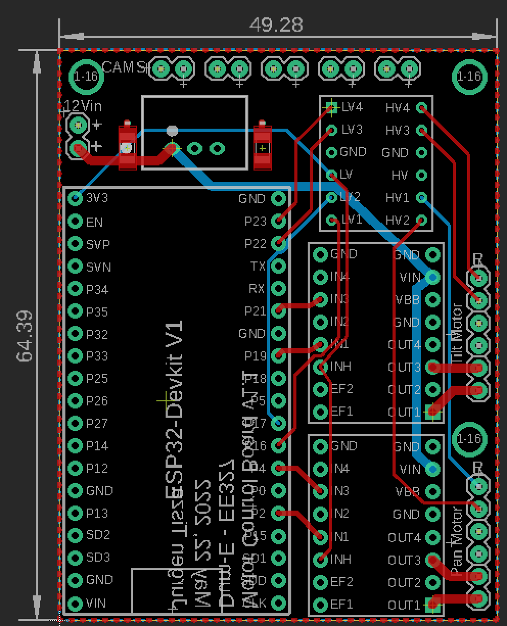
Figure E: PCB
This PCB is able to be wired to two motors, and 5 ESP-CAMS. Unfortunately, while testing, the ESP32 would refuse to flash or run code while connected to the PCB, showing an error in the original EAGLE schematic. Therefore, we ended up only using the PCB as a simple way to power all the ESP32-CAMs.
Custom Enclosure
The need for a 3D printed enclosure came from the fact that we wanted to use 12V motors as opposed to the micro servos that we received in our initial pan-tilt kit. In order to incorporate the motors we needed a custom enclosure that met the following design requirements:
- Able to house four cameras, each pointing 90 degrees away from each other
- Able to house a 64.39x49.28 mm PCB
- Able to provide pan and tilt functionality using both motors
- Able to hold a camera and provide a full range of motion using the aforementioned pan and tilt functionality
Each design requirement was crucial to our project and needed to be implemented in the enclosure in some way. In order to design our custom enclosure we used OnShape.
Overall Assembly
In Figure E the overall assembly of our custom enclosure can be seen. The biggest design challenge we faced was how to incorporate pan and tilt functionality in a 3D printed enclosure. In order to tackle this challenge, we decided that it would be best to split the enclosure into two parts. The bottom part is the camera and electronics housing which as the name implies, houses all the core electronic components. This bottom part also contains the motor responsible for pan functionality. The top part is the platform that can provide an ESP32 cam with pan and tilt movement.
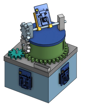
Figure F: Overall Assembly
Box Electronics Enclosure
In order to have four cameras each pointing 90 degrees away from each other, the simplest implementation was to create a box enclosure, with mounting holes for female headers on each side of the box. These holes were sized for 1x8 female headers and were spaced to accommodate for the pin spacing on the ESP32 Cam Devkit. The extruded ring seen in the corner of the box is a slot to place the motor responsible for pan functionality. This part is shown in Figure G and the dimensions of the enclosure itself are 100x100x70 mm.
Figure G: Box to container four cameras, PCB, and pan motor
Box Lid, Bearing Pivot, and Wire Guard
The lid for the box is shown in Figure H. The lid has one circular holes to allow for the collar of the motor to fit into, as well as two smaller holes for screws to mount the motor to the lid. The lid also has a hole for wiring from the tilt motor and main ESP32 cam to connect to the electronics within the box. The wire guard is meant to go over this hole so that the wires do not lay against the lid. Wires laying against the lid are problematic because they can easily be caught in the gears for the pan platform. The pivot is for a bearing to be mounted on to allow for easier rotation of the pan platform.
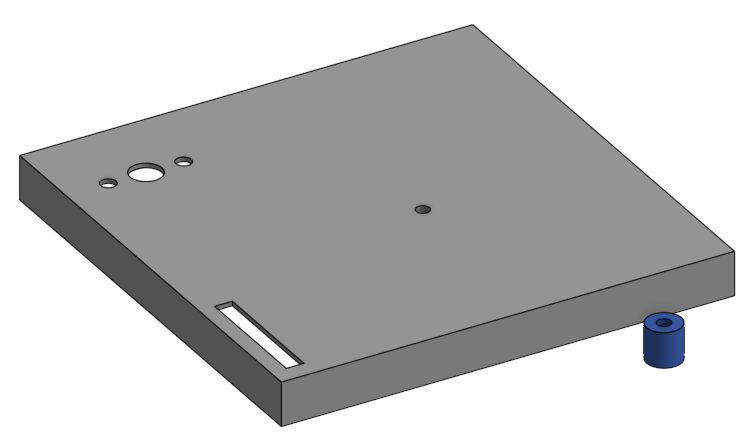
Figure H: Lid for box enclosure, bearing pivot, and wire guard
Pan Platform
In order to achieve pan functionality, we decided to use a platform on top of a gear that could be controlled by the pan functionality motor. This platform can be seen in Figure I. It is important to note that the platform and the gear are referred to as separate entities to simplify explanations, however they are one combined piece. There are three circular holes on a portion of the platform which are meant to fit the tilt motor collar as well as screw holes to allow mounting of the motor to the side of the pan platform. A rectangular hole is cut on another portion of the platform to provide an easy path for the tilt motor wires to reach the bottom enclosure. As shown in Figure I and Figure J there are supports to hold the tilt motor up. This is so that the tilt gear that will be attached to the motor does not interfere with the gear the platform is on. Figure J shows a hole in the middle of the platform which is meant to fit a bearing. This bearing is attached to a pivot which allows the platform to spin easily. The overall gear plus platform combo is 41mm tall and the gear has a pitch diameter of 84 mm.
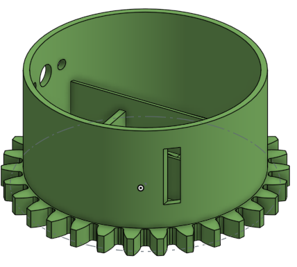
Figure I: Pan platform that contains tilt motor

Figure J: Top down view of pan platform
Pan and Tilt Frame
The pan and tilt frame, although consisting of many entities (including the pan platform), is the final part in our design and can be seen in Figure K. Gears are used to achieve pan and tilt functionality. The pan gears have a 1:3 ratio with a gear module of 2.8mm. The tilt gears have a 1:1 ratio with a gear module of 3mm. One constraint faced with pan motion is that the tilt motor wiring comes out from the side of the pan platform, which may restrict moving. In our testing however, the platform has 360 degrees of motion before the wiring loses slack, so the camera can at least make a full rotation. The overall pan and tilt frame was not printed as one entity. The entities that make up the frame are the pan platform, the pan platform lid, two support pillars, one pan gear to attach to the pan motor, one tilt gear to attach to the tilt motor, one gear with a rod to go through the support pillar holes, and a frame that would allow mounting of female headers to hold the ESP 32 Cam.

Figure K: Pan and tilt frame
Final Product
The final product has two main components: the physical sentry and the web interface in which the users control the sentry through.

The web interface, which is served directly via the Python web server, gives the user the ability to control the sentry. This includes turning on and off the manual mode and controlling the sentry manually via a D-pad. A screenshot of the web interface is shown in Figure L. The top two streams are that of the sentry: the left image shows the raw image taken by the camera, and the right shows what the image tracking algorithm currently tracks. The four streams on the bottom are those of the surrounding cameras. Also on the top left corner of each stream are the stream’s frame rate and round-trip-time. These statistics are included to help identify and debug latency issues
Notice there are three additional switches on the web interface. Initially, we hoped to use these switches to configure the sentry to track targets based on specific properties. For example, maybe we can tell the sentry to only track red targets, only “fire” at specific individuals, etc. These new additions, however, may require using more advanced detection techniques: to identify specific individuals, we may need to use deep learning techniques as opposed to the simple Haar cascade classifiers.
The physical sentry is shown in Figure M. For the assembly of the sentry itself, all components either snapped into place or were hot glued together. The bottom electronics box holds the motor that controls the pan portion of the sentry, the surrounding ESP-32 CAMs, and a PCB with a normal ESP-32 and a motor driver. The top pan platform holds the second motor that controls the tilt portion of the sentry. On top of the pan platform are the pillars and gear with a rod coupled to it that holds the female header mounting frame which allows mounting of the ESP32 cam.

Figure M: Assembled Sentry