John
JohnOur current desolderer project is focused on automatically desoldering electronic components. For this phase, we're looking at taking apart projects that were built at home (devices built on an assembly line will be a later phase). We feel home projects are the most valuable first phase; if you used the component once, it'll probably be useful to you again. We break down our project into 3 main focus areas:
Identifying Solder Blobs
The system is set up to work automatically so it needs to know what it's looking at. We've trained a machine learning algorithm to look at a picture and identify the areas that have been soldered. On the final device, we use a camera and this algorithm to tell the soldering iron where to go.
Guidance Control
Once we know where the solder blobs are, we need to pass that information along to the machine to desolder them. This is done by moving the solder iron head to the center of the machine learning identification boxes. To do this, we'll have a camera next to the soldering iron, so the guidance system can use relative values (which should help avoid calibration issues on different printers). This data will be translated into G-code and streamed to the device.
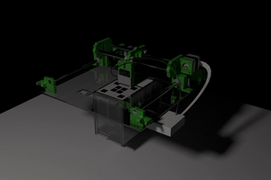
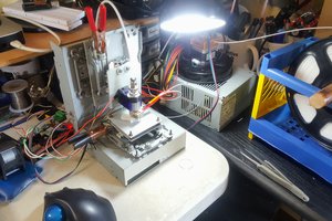
The Hot End
We need a hot point to move to and touch the solder blob to melt it. Since they are so popular in the maker community, we're going to use a normal 3d printer and a basic soldering iron. Upgrading two common devices is more sustainable then using parts to build an entirely new device (that will take up space on the benchtop). Neither the 3d printer nor the soldering iron will be destroyed in this build, both can be used for their original at any time. Our process may require the extruder to be temporarily removed, but we're working to have our sit device next to the extruder so both can be used without spending manual time switching them in and out.
Licensing
We're using the MIT License, which is Open Source Initiative Approved. We really hope that others take what we've done and go even further. The world needs it.


 AccidentalRebel
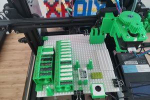
 xpDIY
xpDIY
 The Lab Guy