Emilio P.G. Ficara
The ESP-01 WiFi module was the first one I used, many, many years ago. It came with a firmware version that allowed you to start working using AT commands. There was no Arduino version yet, so early experiments were all based on using an external micro, which used the powerful (and low cost) WiFi connection capabilities of the module.
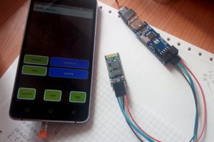
Now things have changed. A lot! With the Arduino development environment it’s possible to create so many applications using only the ESP-01 module, properly programmed (no longer with AT protocol). The beauty of Arduino is that it runs on both Windows and Linux and this makes development really possible for all enthusiasts. The only downside of the ESP-01 module is the very limited I/O lines (note: a new 'F' version is available now, with the same name, but much more I/O; it looks almost like the “old” ESP-07). So I thought of making my own I/O expander connected on the two pins of the TX and RX serial port. Here is what came out:
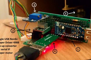
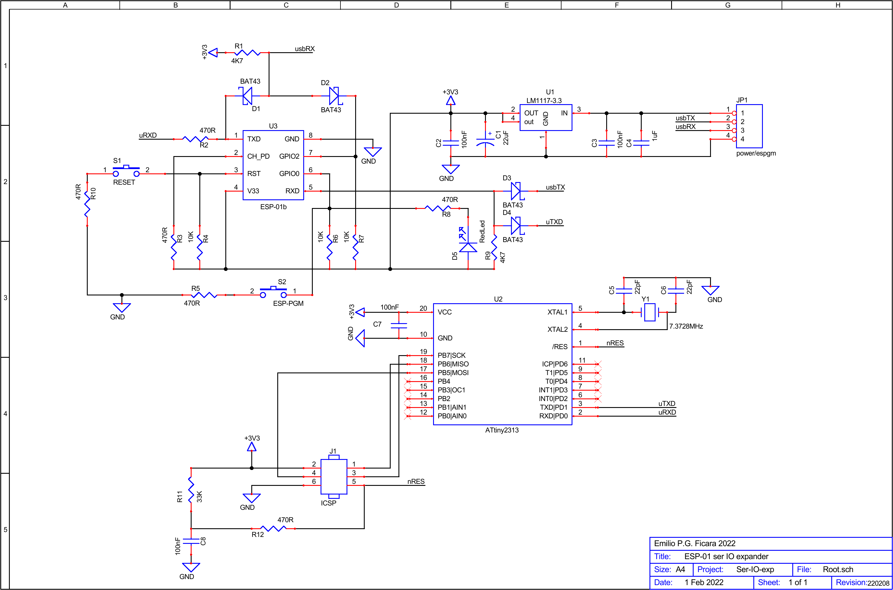
The photo shows the prototype and the removable USB-Serial interface that is used both to program the ESP-01 and as a debug serial monitor. The circuit is powered at 5V and has a 3.3V regulator for the microcontroller and ESP-01. Here is the complete schematic (note that the RGB LED visible on the prototype is not on the schematic, but is part of the "demo" you will find on the ESP-01 application for Arduino):
If you want more detail, you can download the pdf from the “files” section.
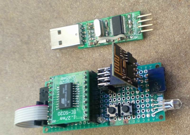
A brief note on the USB-Serial interface used in this little design. It is based on the PL2303 and has only 4 pins. I made a small modification as seen in the picture:
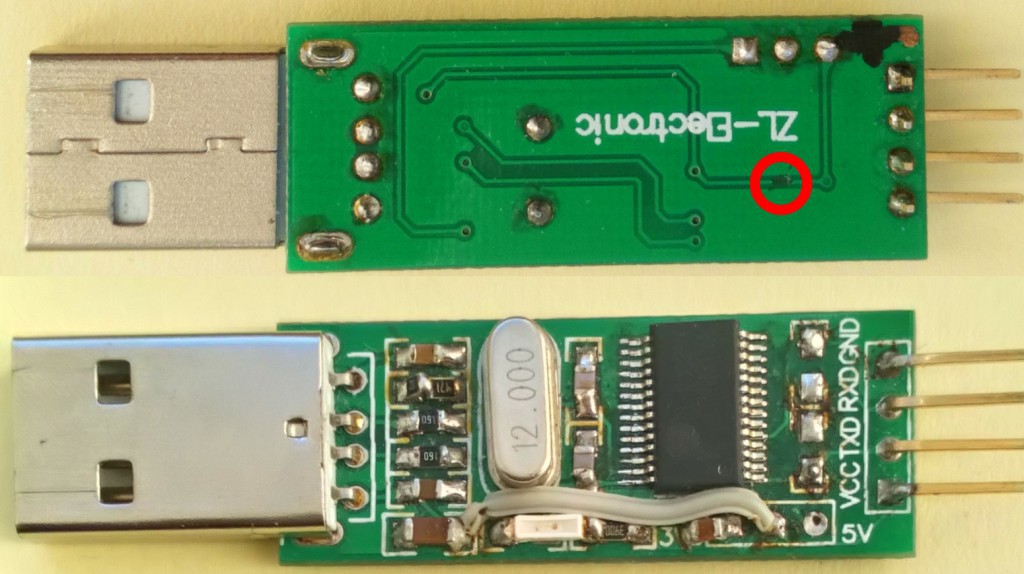
There is a track cut (red circle, top) and a wire jumper, plus a small cond. 100nF (bottom). This is to make sure that on the VCC pin there is 5V coming from the USB and instead the TXD and RXD signals are 3.3V. With other interfaces it is possible to do the same thing without cutting or soldering. Note that the circuit is assembled "by hand," because I had chips and PCB available from an old online purchase.
As you can immediately see on the schematics, there is a microcontroller type ATtiny2313 which is our I/O chip. To the question, "why that one?" I answer, "because I have a lot left over from an old project". Obviously, to perform this task, the micro must be properly programmed. I developed the firmware in C with the IAR's KickStarter for AVR, which can be downloaded (after free registration) from the manufacturer's site. The free, unlimited time version allows you to develop projects up to the 4K limit, which is absolutely no problem since the micro has only 2K flash!
In the “files” section you will find the complete project folder, with the source file in C and also with the hex file for those who want to program the flash directly without making changes.
Adding commands to the current ones is easy, just copy-paste one of the current ones and modify letters and operations to do appropriately, then recompile and reprogram the micro with the new version. The current commands are bare bones, but enough to do anything. Little work on the micro means that more will have to be done on the ESP-01 side, but this has enormously more resources, so logic tells us: get the resources where they are!
Here are the contents of the working folder:
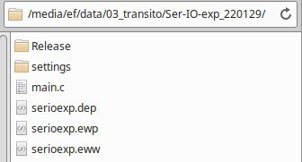
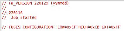
The serioexp.eww file is the one that, with a double click, starts the IAR development environment (if it has been installed!). The main.c file is the source in C, in a minimalist version, which you can expand as you like. The Release/Exe folder contains the serioexp.hex file that can be used to program the flash memory of the ATtiny2313 micro. If you do not want to make any modifications, this is all you need. In addition to the flash, you need to program the "fuses." This is the map:
For those who do not want to download the file but just want to take a look, here is an extract from the command parser:
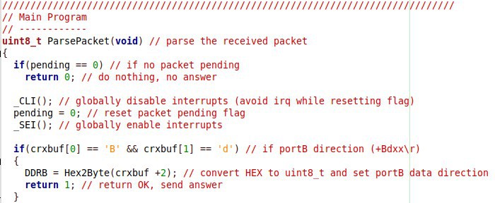
Everything...
Read more »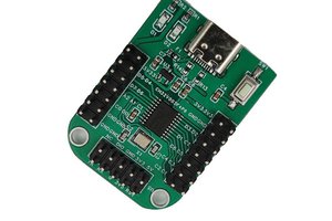
 CanHobby.ca
 Voja Antonic