Obviously this is not the first modification of a Vindrktning (see #IKEA Vindriktning PCB and #IKEA Vindriktning Daughterboard) but I think I did some unique things that are worth sharing.
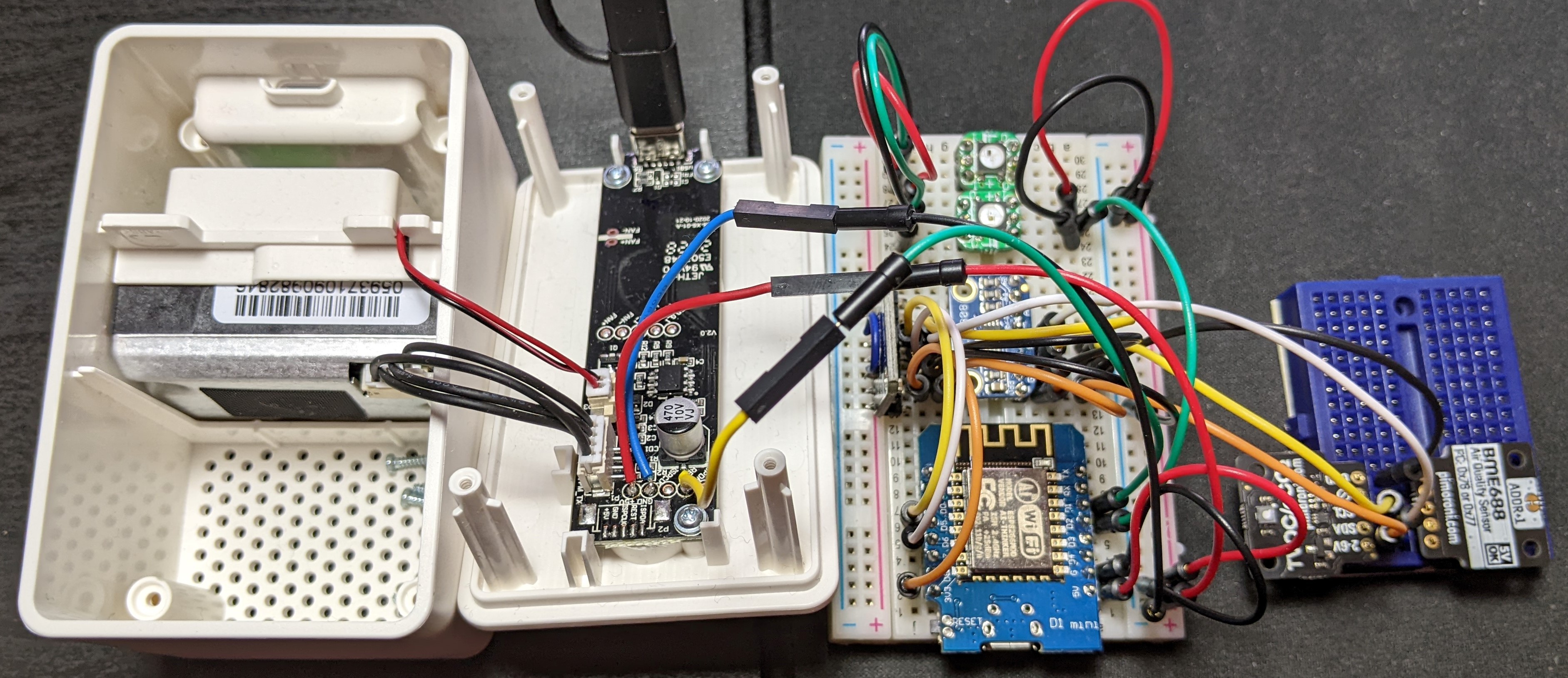
See the project log Inspirations/references for more resources and the files section for my Eagle PCB design.
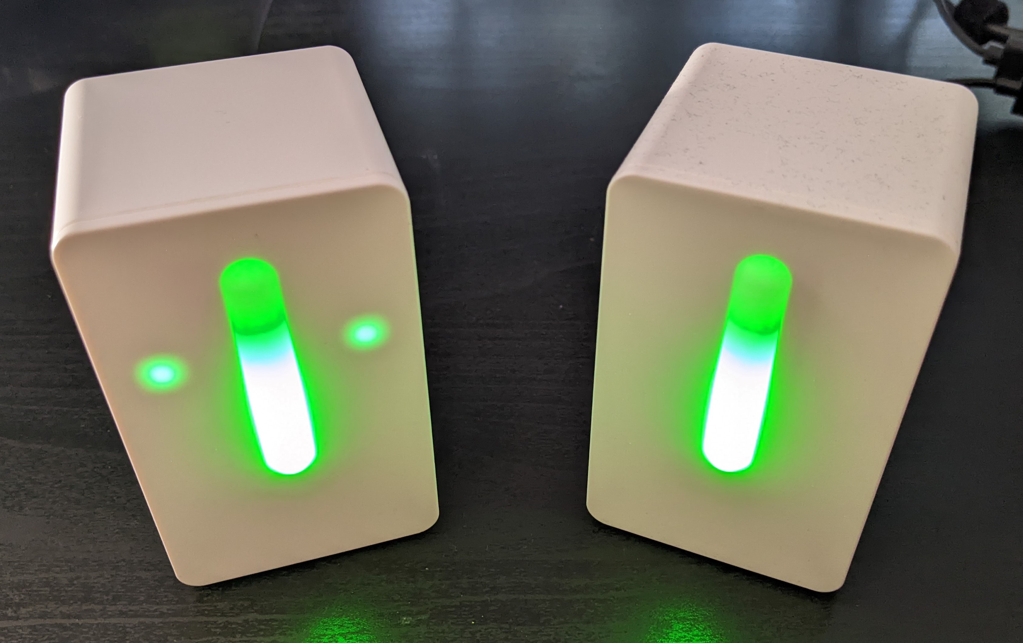
When starting the project I contemplated whether to just go quick and dirty and point-to-point wire everything and stuff it into the Vindriktning case or to go @lond's route and make it more polished. For just attaching the Vindriktnings PCB to an ESP8266 I would probably have point-to-point wired it but since I wanted to add sensors and LEDs the wiring would get too elaborate and a PCB would be the way to go, so might as well make everything a bit more polished. Meaning custom PCB, neat wiring, connectors, 3D printed LED mounts and LEDs for the additional sensors to mirror the Vindriktnings LEDs for displaying PM2.5 levels.
I started with a CCS811 and MCP9808 and then added a BME688 and SGP30 to be used in the final implementation.
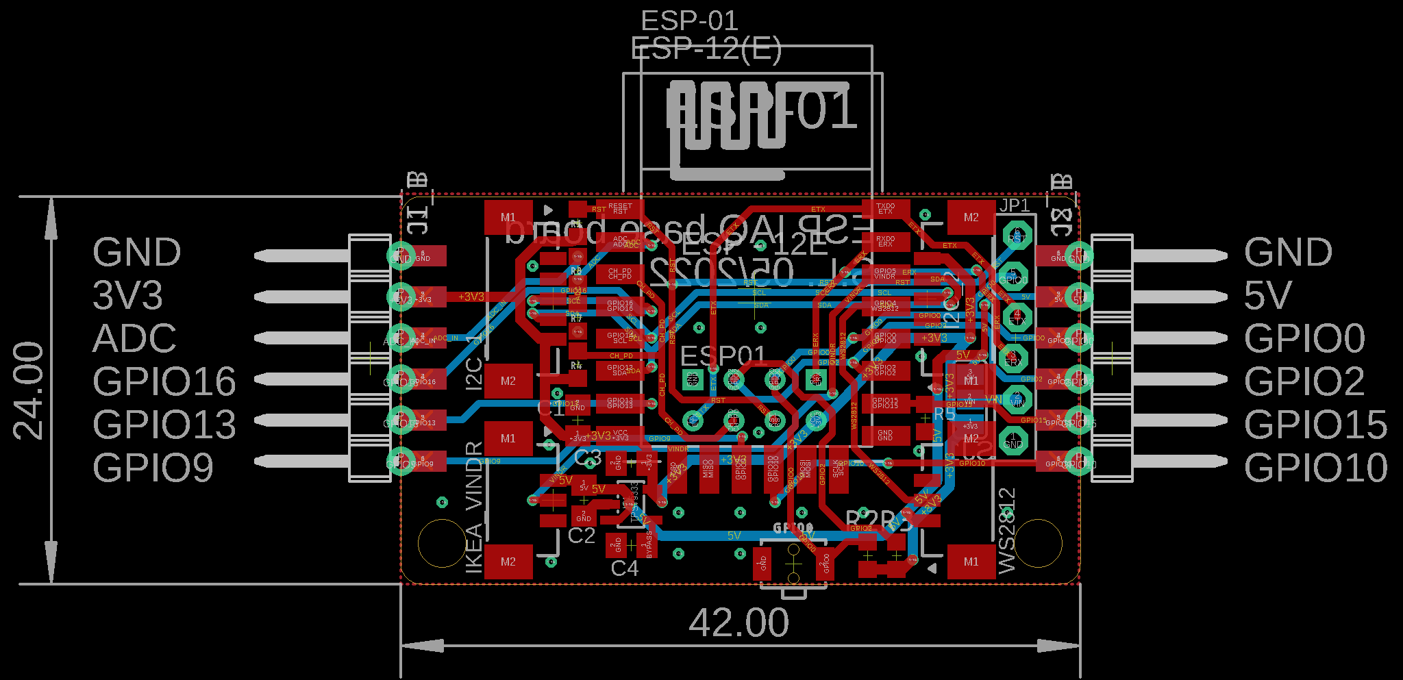
Unfortunately, #IKEA Vindriktning PCB doesn't include the schematic and board files and I didn't see #IKEA Vindriktning Daughterboard until after I was done, so I designed my own board starting from an older ESP breakout board of mine.

I had to switch out the regulator from a SOT223 package to SOT23-5 but let's not talk about sourcing those atm.
I wanted this board to be versatile and not only meant for this one purpose or give people the option of using other devices and for example the ESPs ADC. Therefore, besides connectors for the Vindriktning, the I²C sensors and the WS2812 LEDs I routed a few more GPIOs to castellations at the board edges.
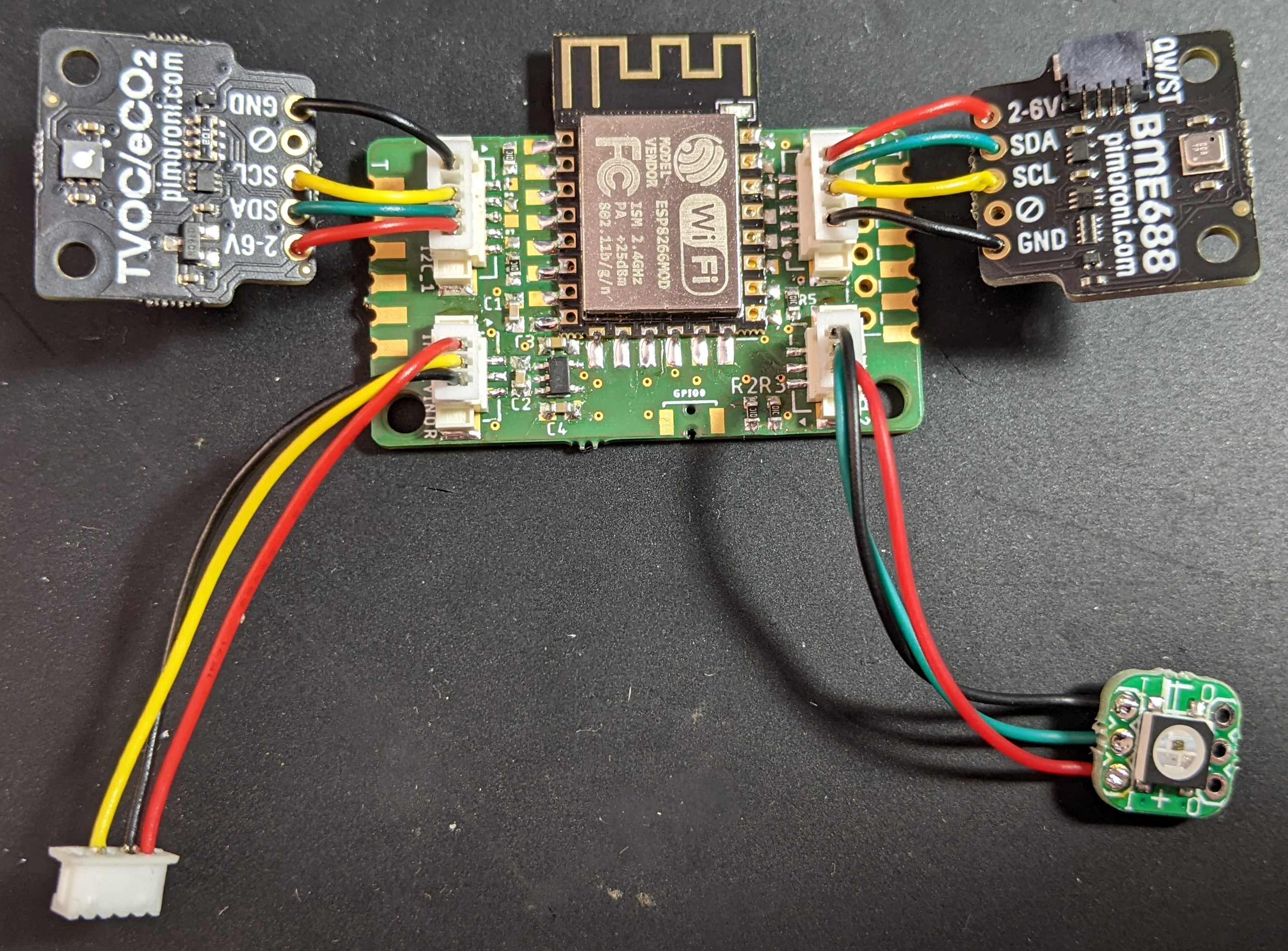
I also thought about using some of those daisy chainable sensor breakouts from Adafruit but wasn't able source them or find precrimped wires that were short enough for my purposes. As you can see I landed on the breakouts from Pimoroni, gave each sensor its own connector and cut down and reconfigured precrimped PicoBlade wire assemblies.
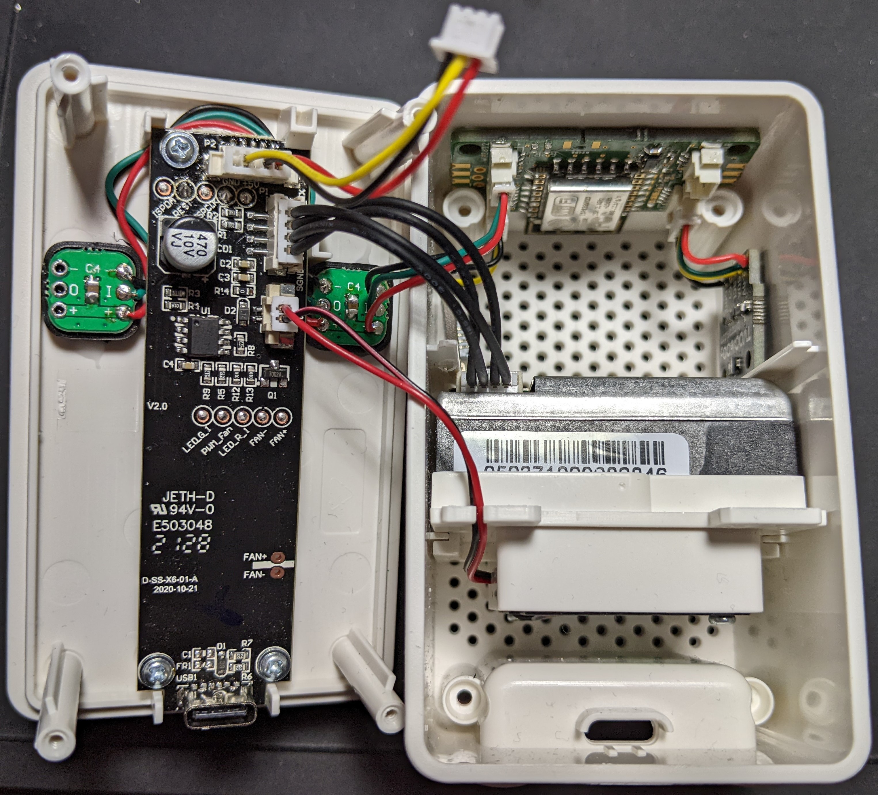
From there it was just a matter of putting everything in the case...
... and configure the software side.
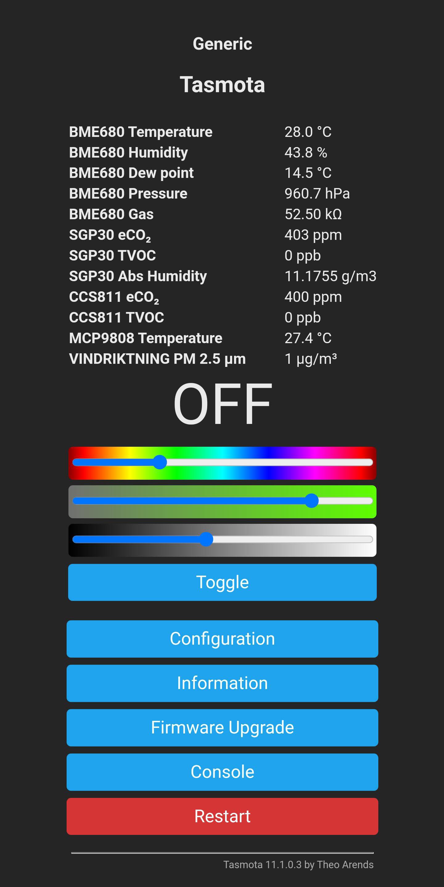
As you can probably imagine, I used Tasmota to publish the sensor readings via MQTT and store them on a Raspberry Pi. I won't go into details here but you can find the instructions I followed in Inspirations/references. Besides the visualization in a Grafana dashboard I set up some flows in NodeRed to send color values back to the ESP according to the sensor measurements and thresholds, one for eCO2 and the other one for TVOC.
-----
Edit 2022-07-01: Updated schematic image
 Stefan Lochbrunner