 samm928
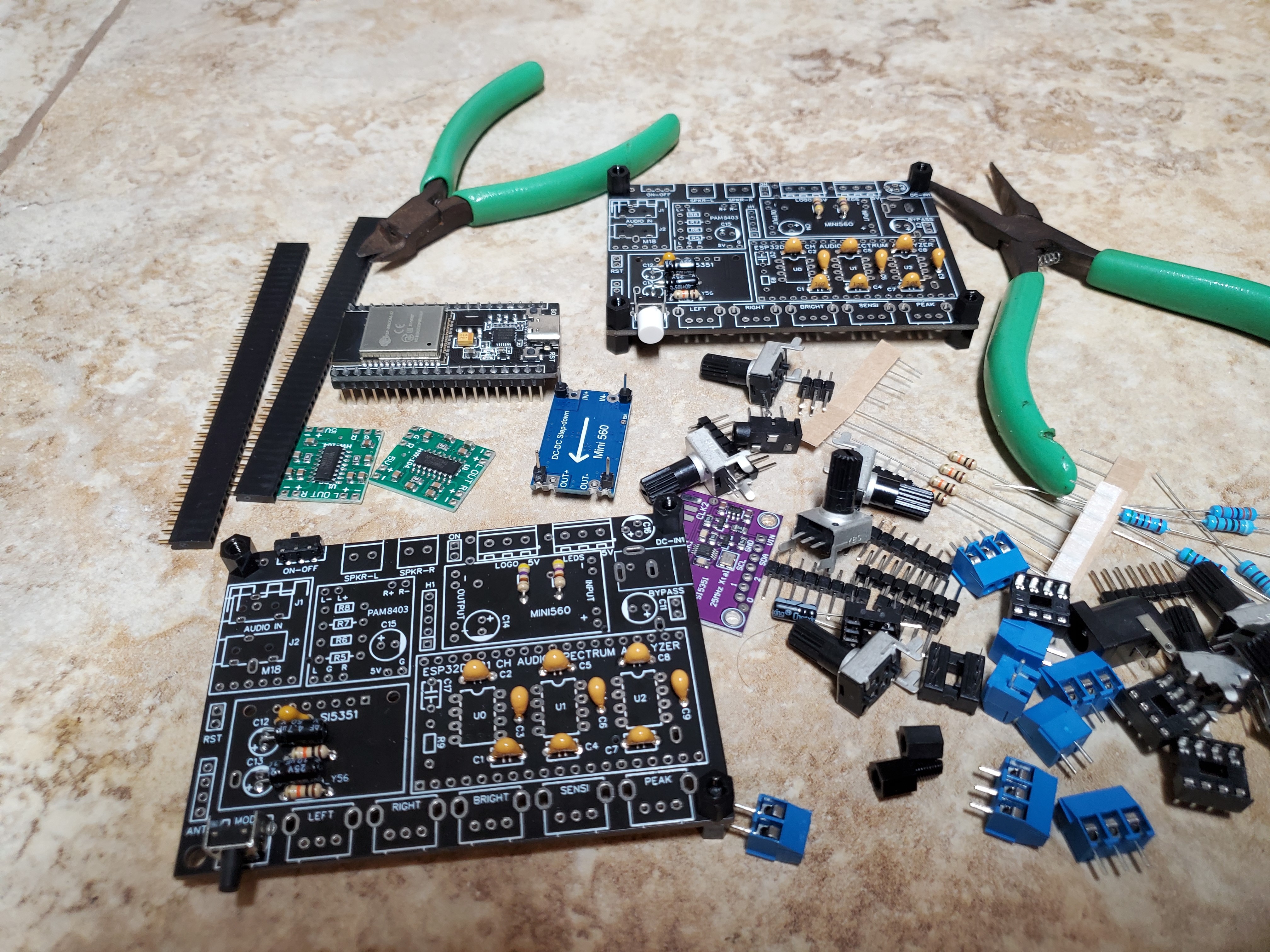
This project started as a hobby using a generic 14-bands spectrum analyzer based on Arduino AT-Mega, and converting it to a 21-bands audio spectrum analyzer now running on ESP32 with more memory for additional color patterns and features. New hardware includes the low cost 2x 3watts Audio Amp and Bluetooth connectivity.
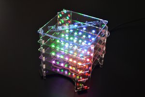
The biggest challenge was making the LED bezel / 20x 21 LED array. I ordered separate vertical columns for the LED strips to stick on, and then solder the two ends to 3-pin terminals. I also ordered the 2 horizontal PCBs that holds the 21 columns and distributes power to all 420 LEDs .. Using the LED Strips with the PCB was the easiest way I could think of without having jumper wires between the 21 columns ..
A second variant, which I will try in the upcoming weeks, is to hand solder the 420 LEDs individually which will save me about $40 and will look much nicer. I will try and use low temperature solder paste (138degC) and a heat gun to blow hot air from below the PCB. I'm not sure is going to work, but using a hot-plate will be even more challenging.


 Moritz v. Sivers
 Stijn
Stijn
 Sagar 001
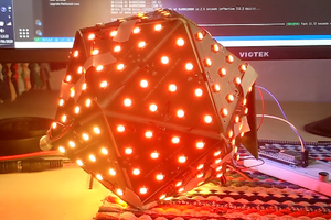
 Myles
Myles
Very nice and hypnotic spectrum analyser