Video Output Hardware
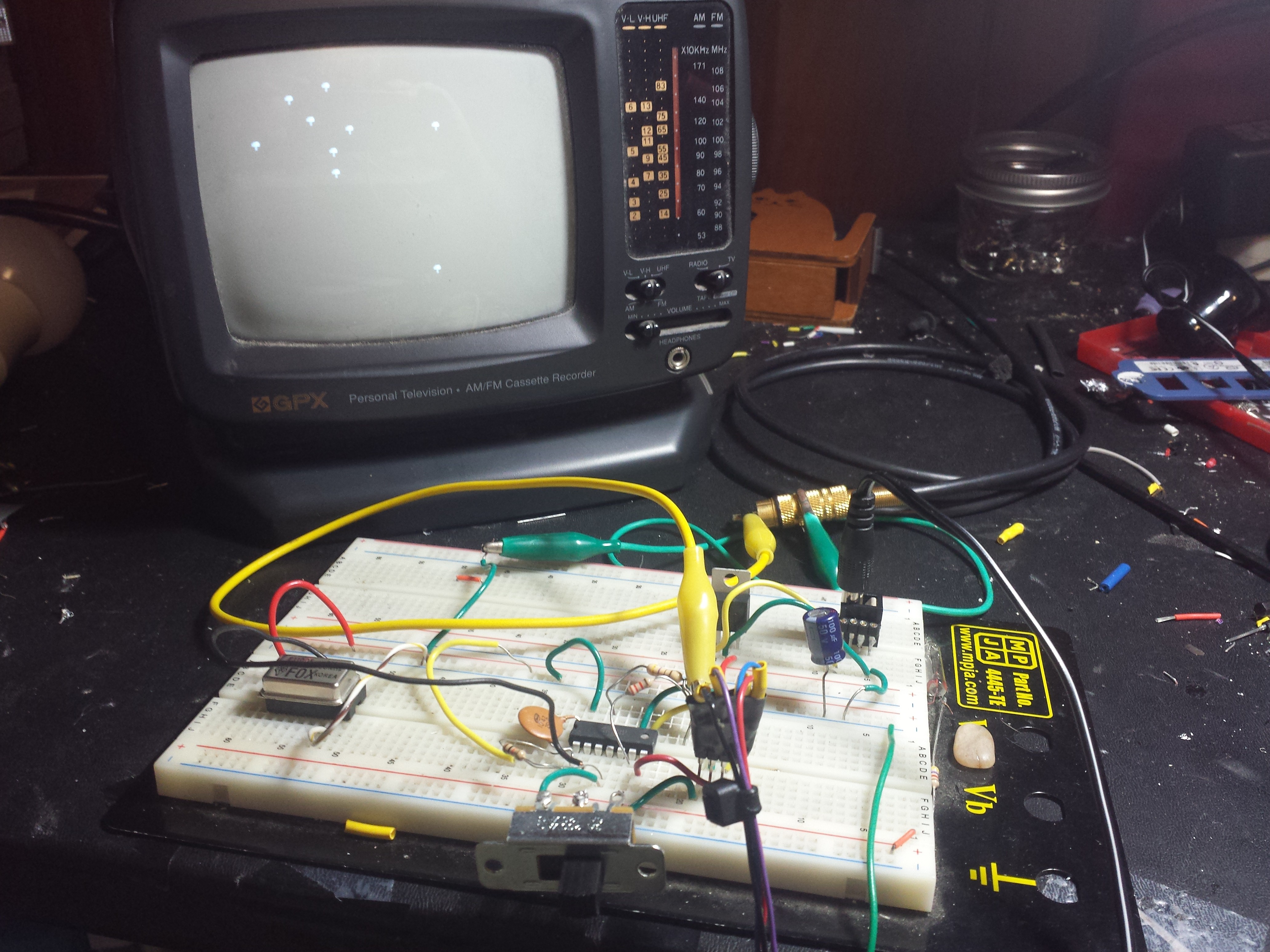
The video output is achieved using just two outputs: One for sync and one for color. These two ports are tied together with a resistor divided and form a crude DAC. This is based off of the Arduino TVout library http://playground.arduino.cc/Main/TVout
Controller Input
The controller input is an Atari 2600 Joystick. The pinout is provided here. http://www.hardwarebook.info/Atari_2600_Joystick I only use Left, Right and Fire for this project.
Video Output Software
I found the TVout software to be very hard to understand. I took 1 small part of it: the wait_until inline-assembly routine. The rest was discarded.
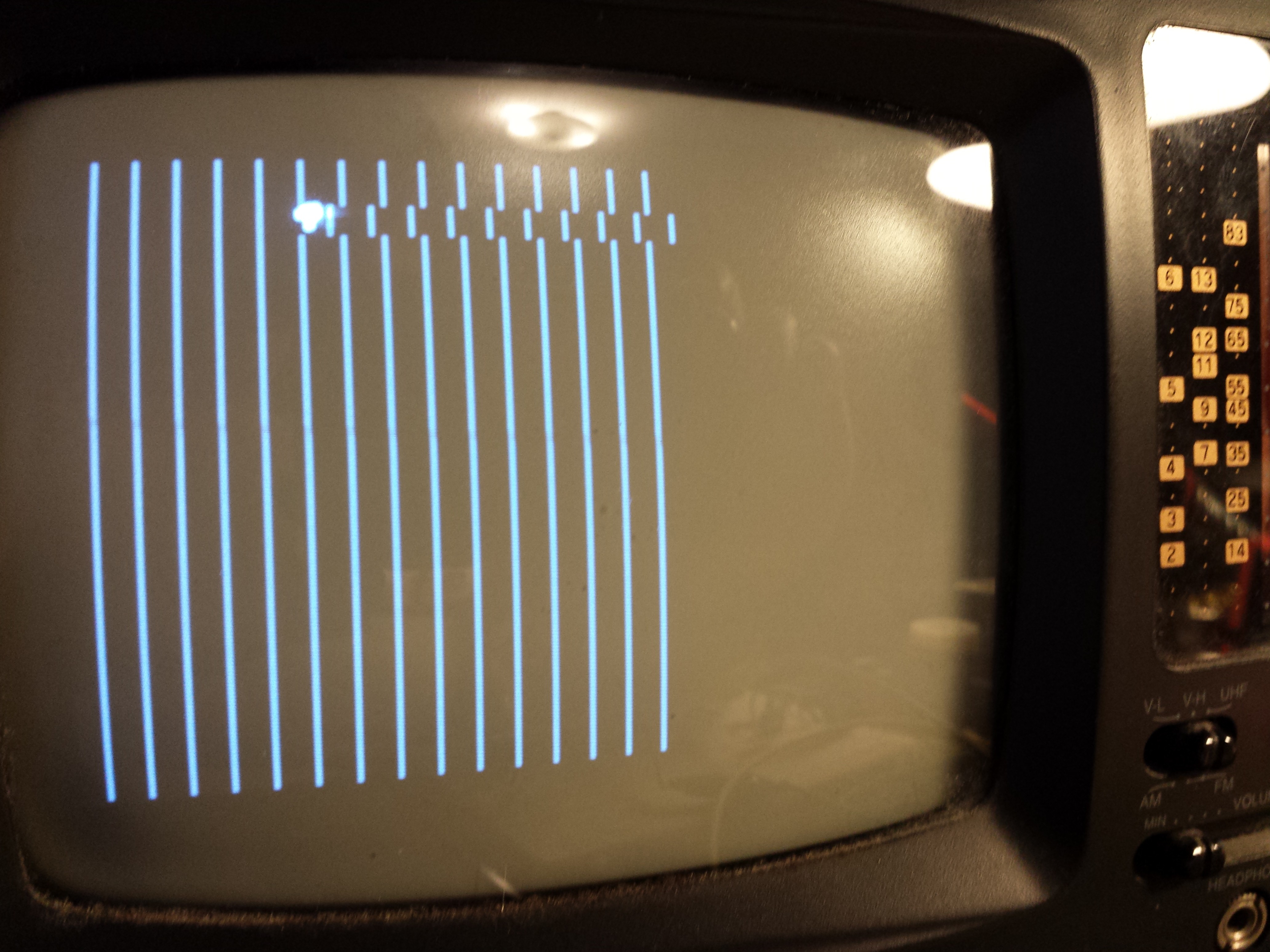
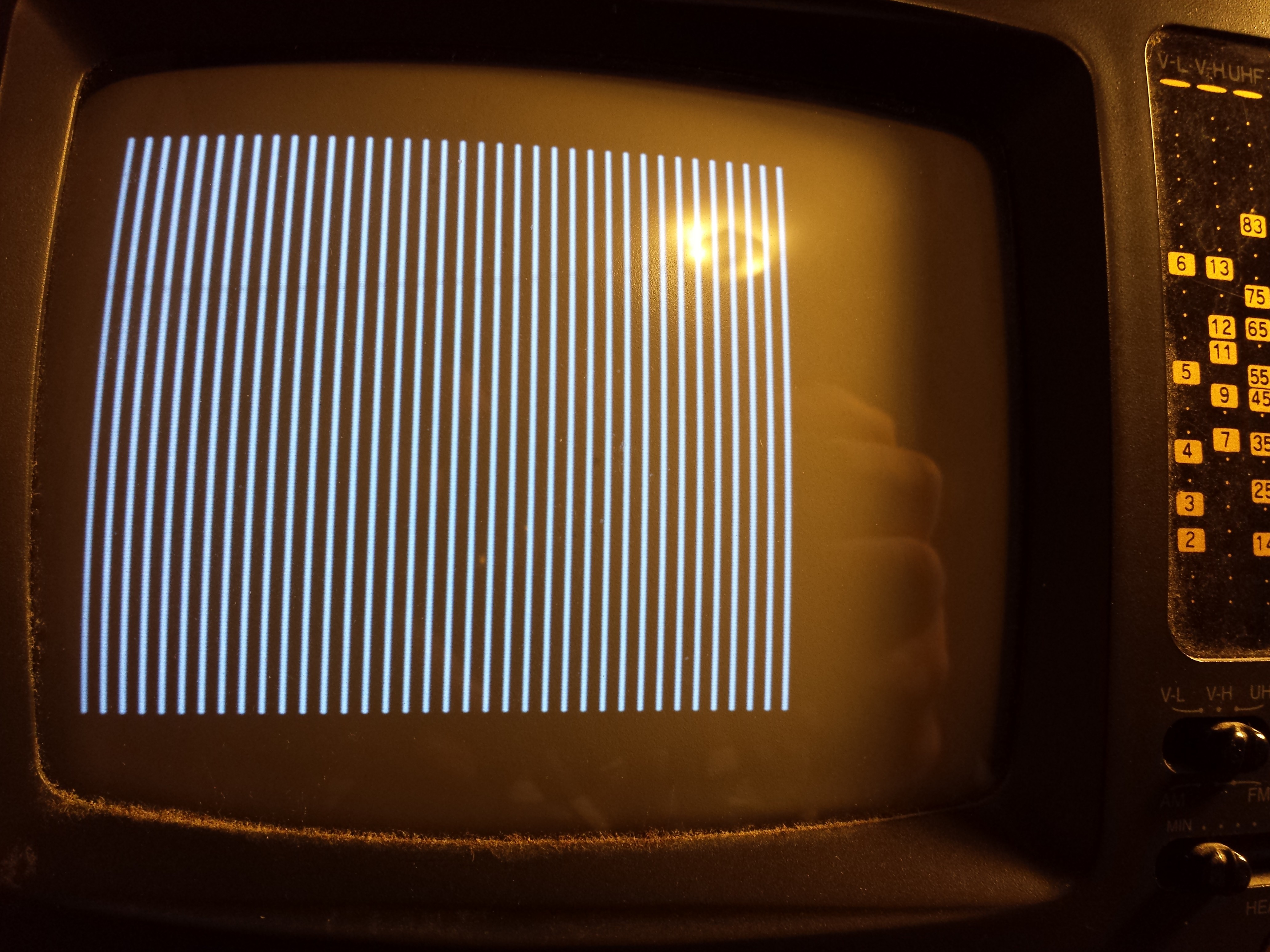
I took some liberties to what constitutes a NTSC signal. After trying to implement most of the spec, I settled on something that ended up being the same thing Atari and other consoles did: A 'hack' called 240P. The screen is not interfaced as usual, and there are no 'odd' and 'even' scanlines. Only 240 lines are drawn every frame, and there are 240 lines on the screen that are black and never drawn at all. If you want some deep details on how full NTSC is supposed to work, visit this page: http://www.ntsc-tv.com/ntsc-index-02.htm For info on how I stumbled upon 240P instead, I have a project log just on screen syncing, so I won't repeat it here.
Racing the Beam
To generate the video signal, the technique used here is called racing the beam. This is exactly how the Atari 2600 generates an image. There is no framebuffer. As the electron beam is scanning the TV, the software must pull the output high, to produce white, or pull the output low, to produce black, at the exact instant the electroncs are shot into the screen glass. This means timing must be perfect. Fortunately for me, I don't have to do much cycle-counting at all thanks to Interrupts.
The Atari 2600 had NO interrupts. The programmer must carefully work everything out during the blanking period and output the signal on-time. Using the Attiny timer interrupt, I can split the program into two threads. Thread 1 is the 'main' thread running game logic. This reads the joystick, and calculates where everything should be on the screen. Thread 2 is the interrupt handler: Every so often, the interrupt fires and the interrupt handler outputs 1 scanline of video. One thing gained by this project is a tremendous amount of respect for the Atari 2600 programmers, who had a much worse CPU and no interrupts. Somehow Pitfall happened.
Video Frame Structure
To represent the gamestate to draw, there are some variables defined:
- playerx: The player x-position
- bulletx, bullety: The position of the bullet the player has fired
- mushrooms[]: sorted char array specifying positions of mushrooms on the screen
- bugs[]: sorted char array specifying positions of bugs
- SCR_COLS (constant) : number of grid-columns in the display.
- scrpos: The screen position the electron beam is point at
- drawpos: A pointer into the mushrooms or bugs array, noting which one is expected to be hit by the electron beam next.
- line: The current scanline number. (line mod 8) is the row to use for a sprite. Hint: (line mod 8) is the same as (line & 7), so no division/remainer is necessary.
The position of an object is just a number representing a point on a grid. The top-left position is 0, the one to the right is 1, all the way up to (SCR_COLS-1). Position SCR_COLS starts the second row, 2*SCR_COLS is the 3rd row. It looks like this:
00 01 02 03 04 05 06 07 08
09 10 11 12 13 14 15 16 17 18
19 20 21 22 23 24 25 26 27
...
A typical mushrooms array might look like { 5, 12, 17, 23, ENDOFLINE}; This would mean to draw a mushroom in positions 5, 12, 17 and 23. ENDOFLINE is the value 255, which serves as a terminator of the array.
Suppose we only want to draw mushrooms. For a given scanline, we can look thru the mushroom array for mushrooms that would appear on our row. We can display a horizontal 'slice' of pixels for a mushroom, or keep the display black, for every position on this row. The mushroom array is kept sorted so that after...
Read more » Mars
Mars


 Mark Wilson
 Timo
Timo
 Wenting Zhang
Congratulations!!!