I wanted to connect replacement LCD to the original LCD connector, with no "ugly hacks" like interfacing with VGA connector and other workarounds. The original LCD used 9-bit TTL RGB interface (3 pins for red, 3 pins for green, 3 pins for red), which understandably is quite dated, especially considering the fact that this was probably the first laptop with color TFT screen.
I was able to only source replacement screens with 18-bit RGB interface (i chose Sharp LQ104V1DW01), with much slimmer outer casing (but the same screen area and resolution). Therefore I needed to adapt new screen both electrically and mechanically.
The original interface had 8 possible values for each color (0,1,2,3,4,5,6,7, or 000 to 111).
On new LCD, there are 64 possible values for each color (0 to 63 or 000000 to 111111).
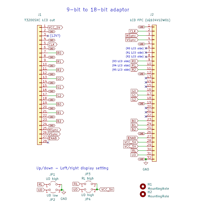
The idea was just to ommit half of the R, G, B pins. The lower pins (RGB0,1,2) on new LCD would remain unconnected. The upper pins (RGB3,4,5) would be connected with RGB0,1,2 from the computer. Now the maximum value for each color will be 111000, which is 56 out of 63. That limits the maximum brightness of the screen to 89%, but this should not be a big deal.

There are also UD (up-down), RL (left-right) pins on the new LCD, which can be pulled either to ground or VCC. They can be used to rotate or mirror the image. I left them floating, however a option of jumpering them remains if ever needed.
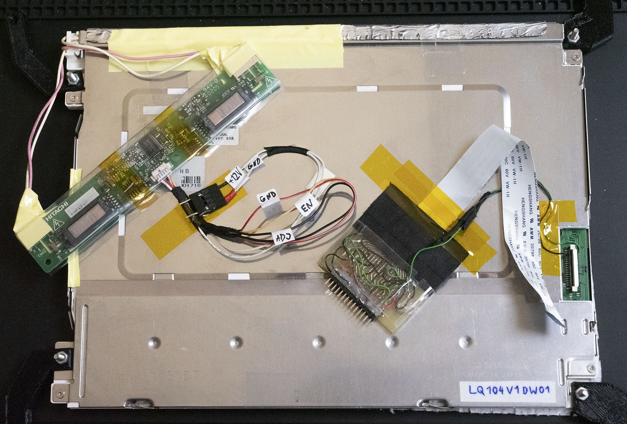
A prototype was produced using a single-sided home-etched (laser toner transfer) PCB, with 2.0mm 28pin header and directly soldered 0.5mm 32-pin ribbon. Because the board was single sided, it required a bit of jumper wires. The screen did work and I partially potted the PCB in epoxy.

The backlight inverter also needed to be hacked, as I didn't have a matching one for the new screen, and I couldn't use the old one. There was no brightness level signal on the T3200SXC, so I had to connect EN pin with ADJ pin. That way the backlight was on as soon as +12V was provided to the board.
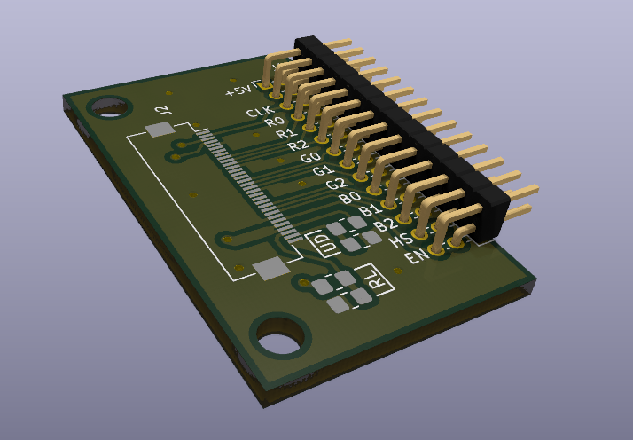
This is how a more production-ready board would look like, with a double sided PCB, pads for FPC connector and some mounting holes:

Discussions
Become a Hackaday.io Member
Create an account to leave a comment. Already have an account? Log In.