 Paulius J.
In iterative development and exploration process, details will be consolidated once I'm closer to something... "final".
0%
0%
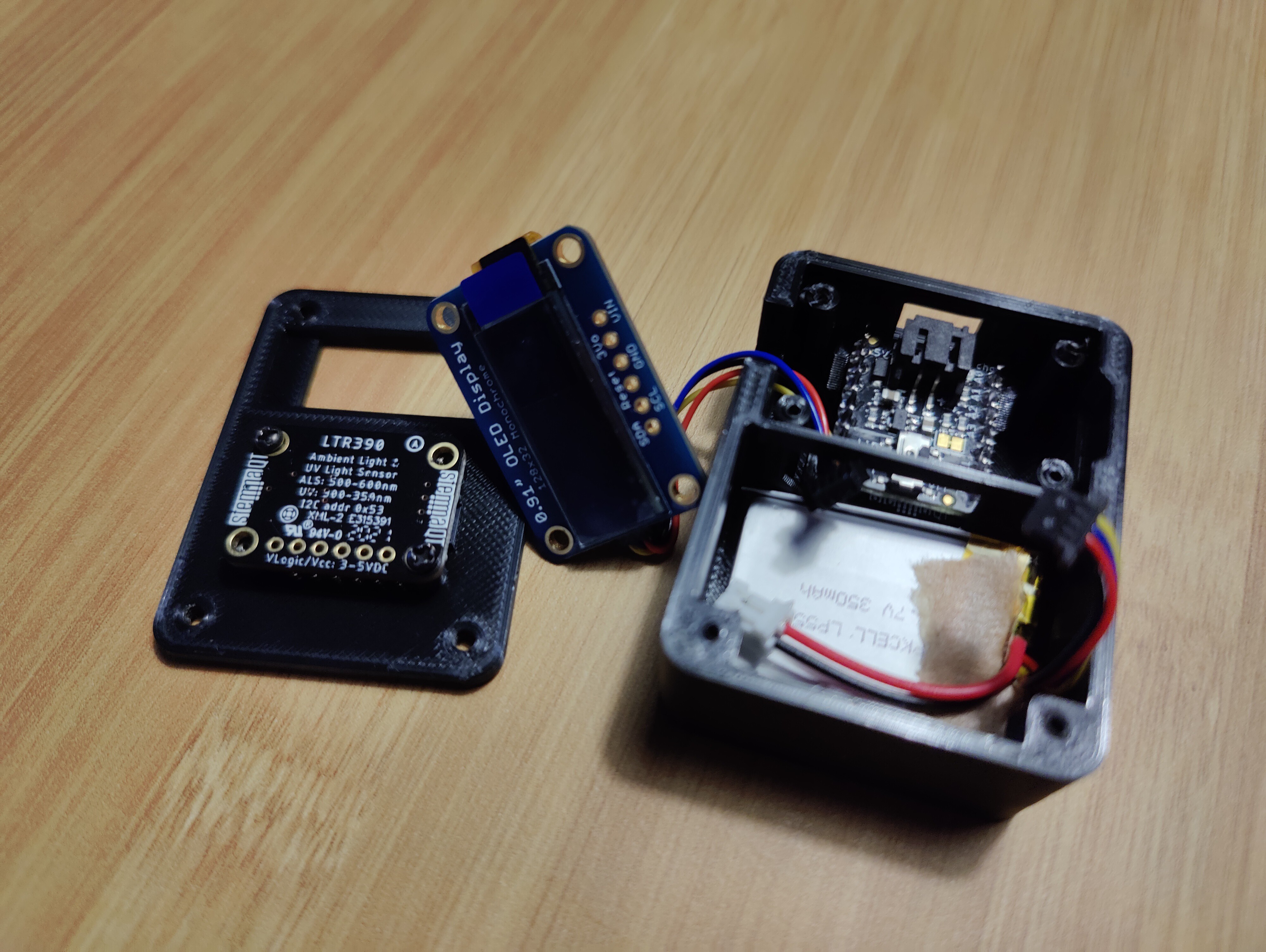
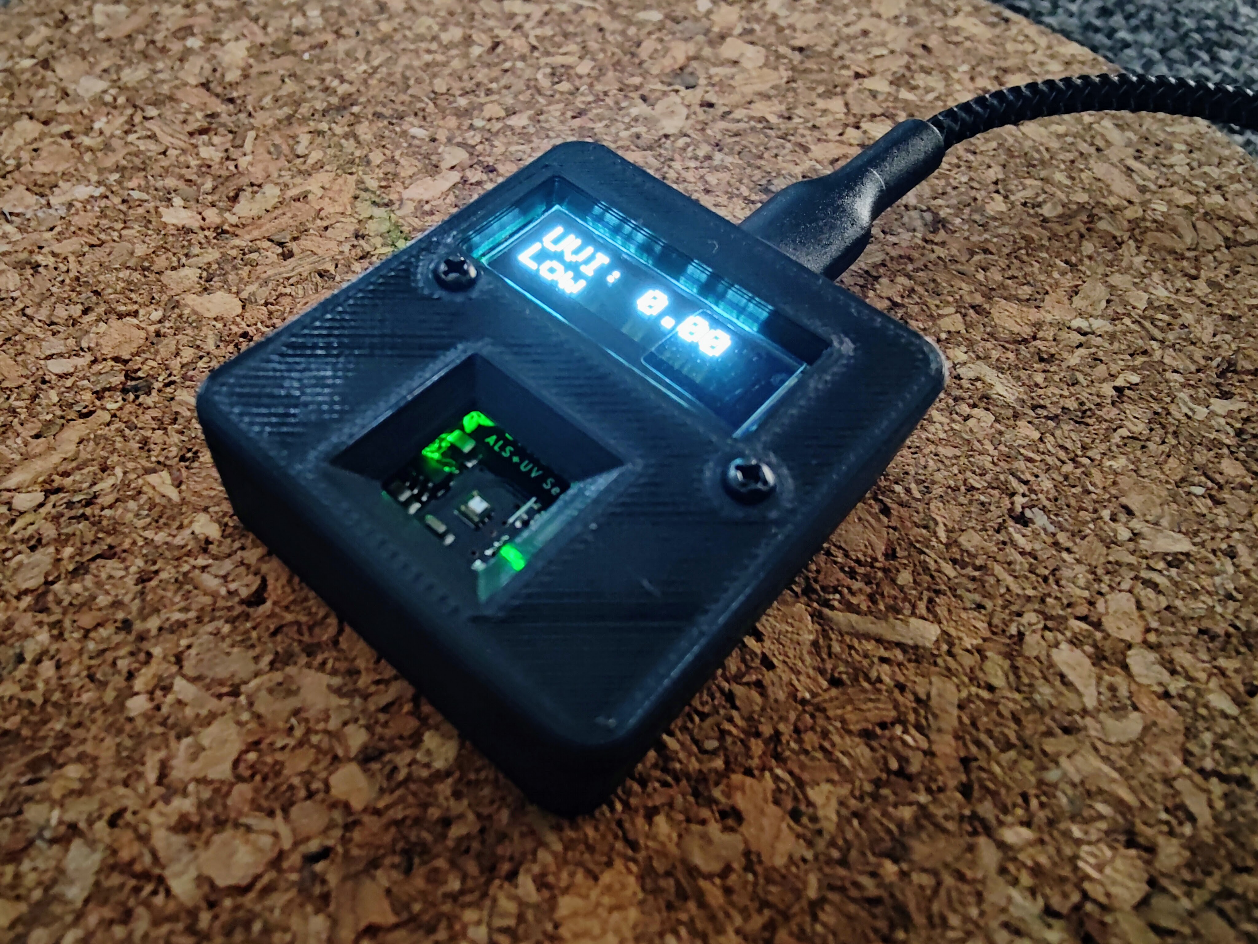
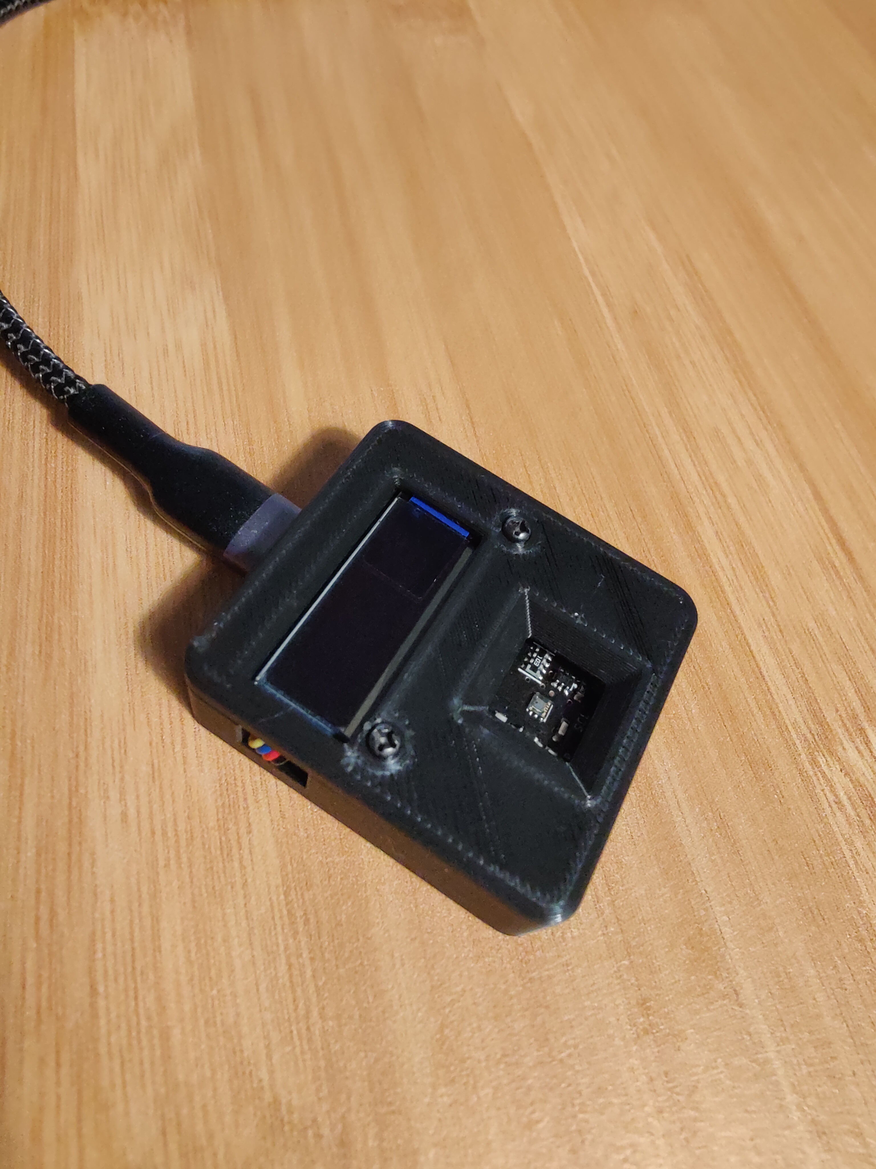
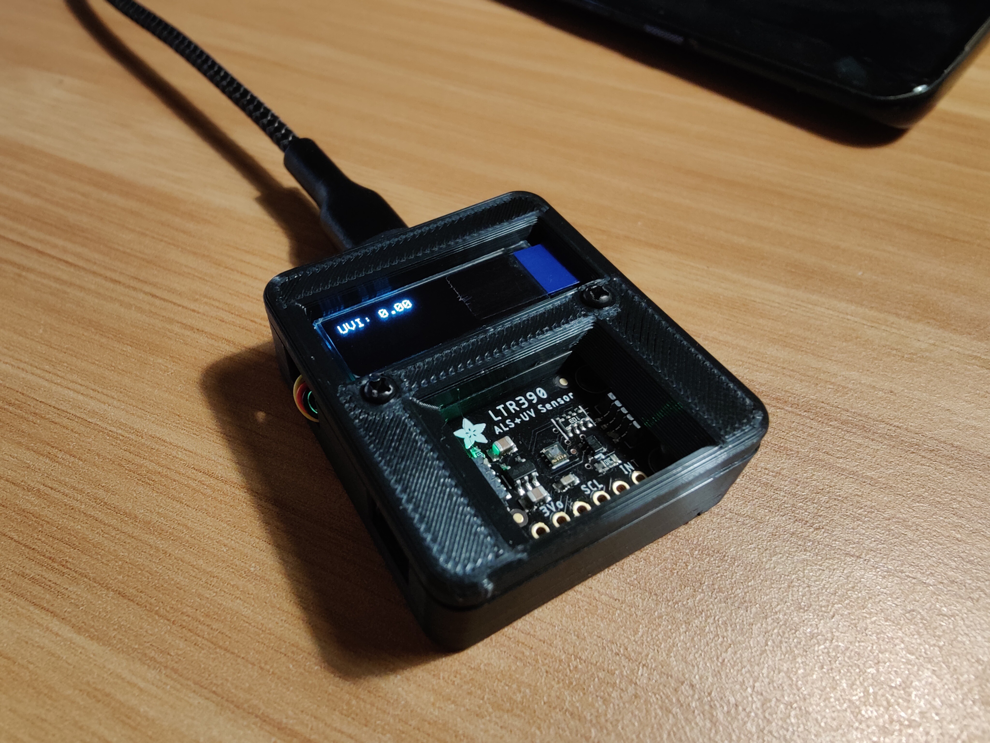
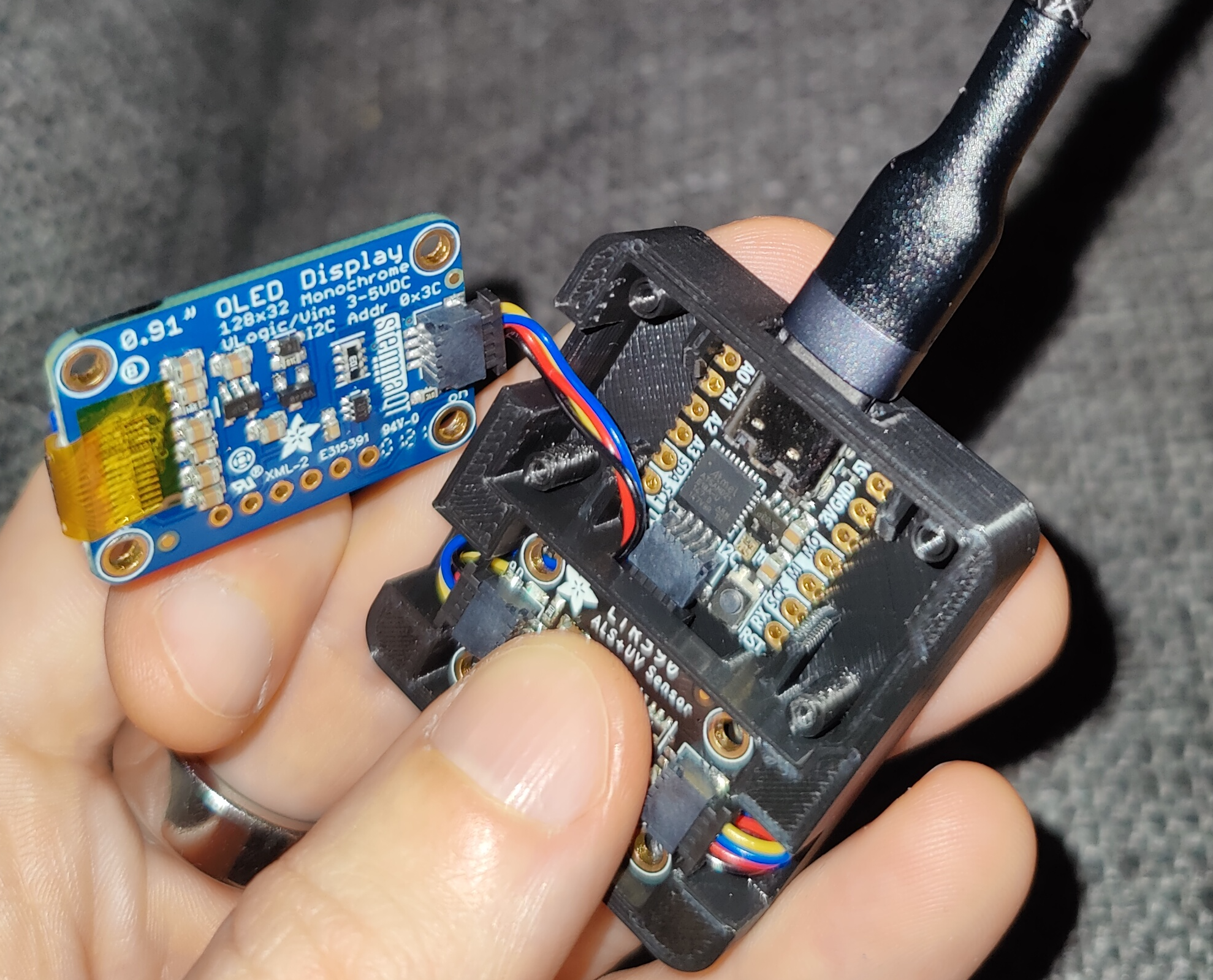
Uvee Py
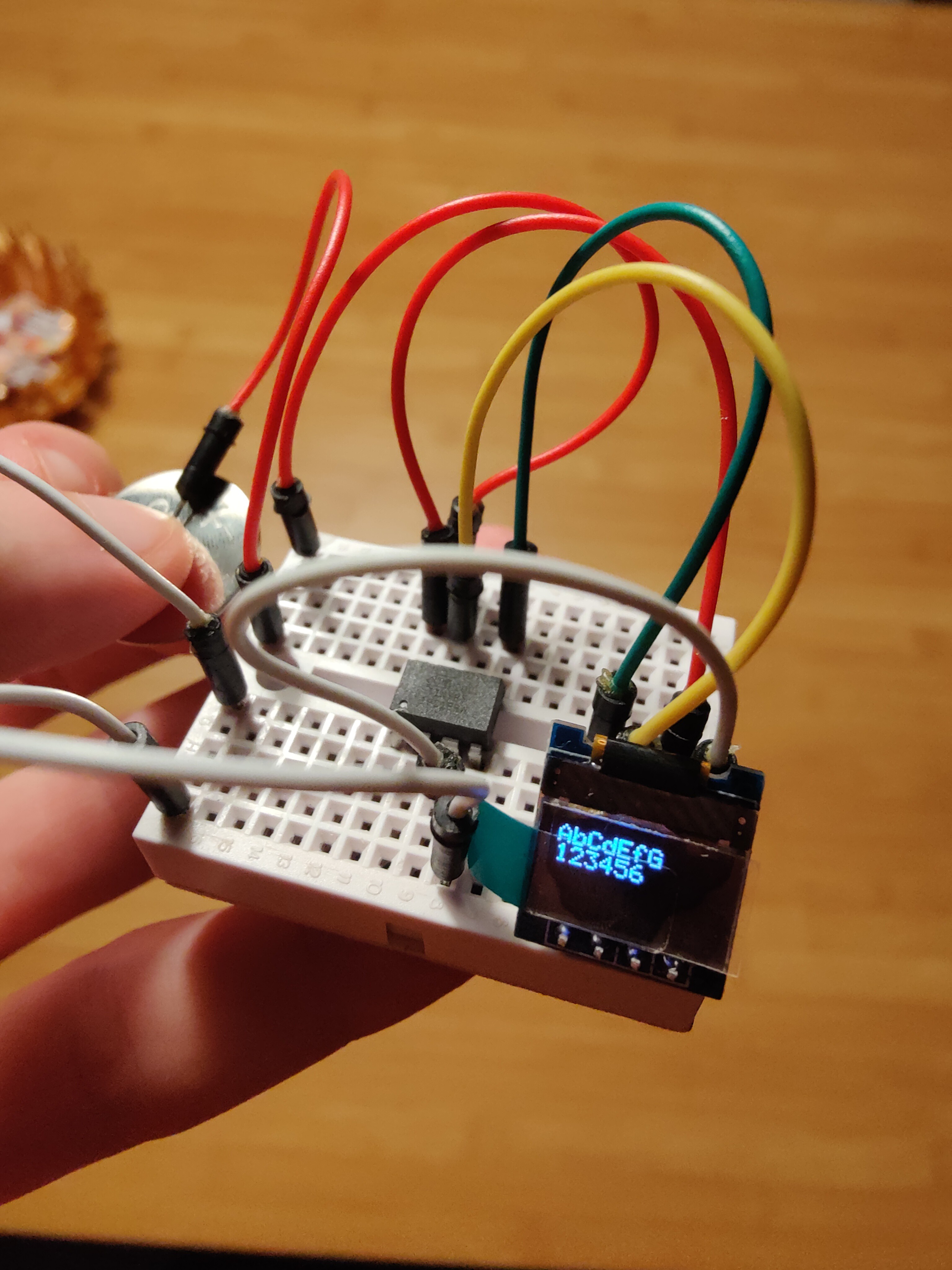
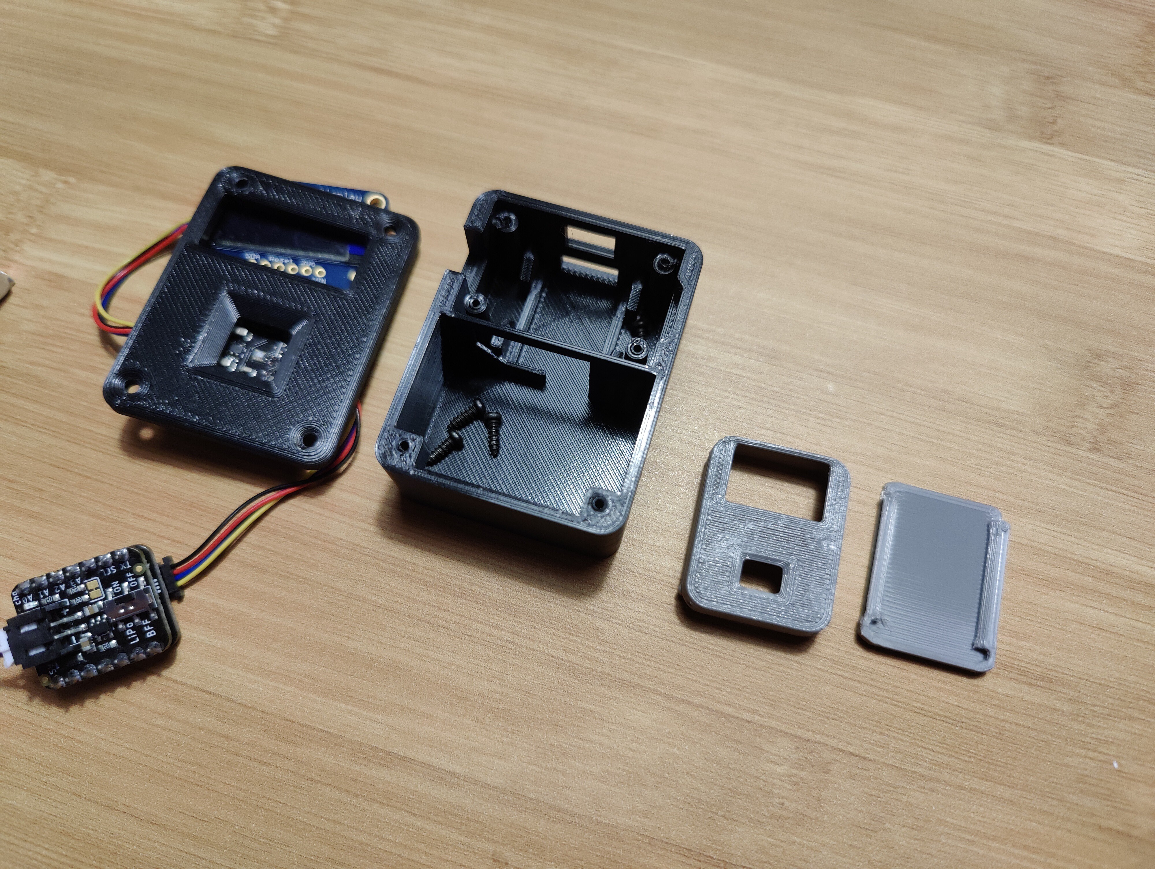
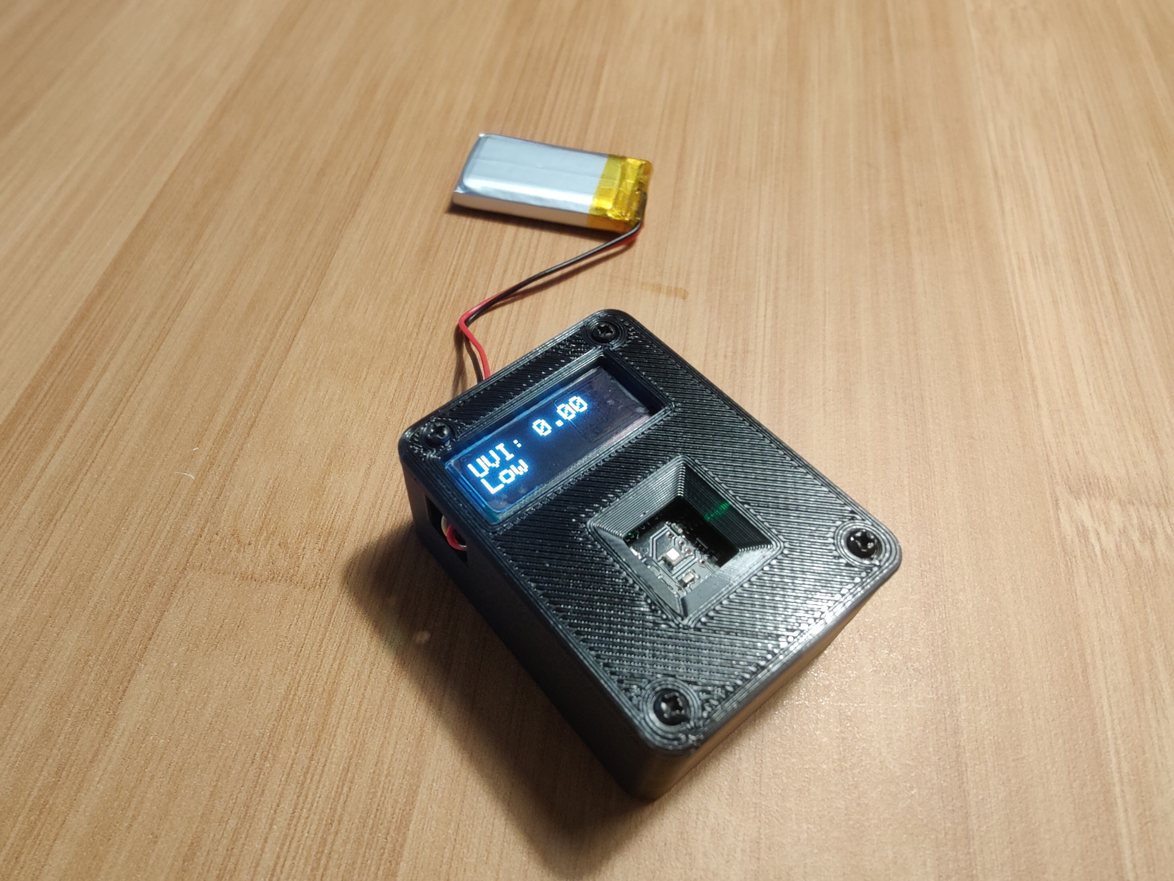
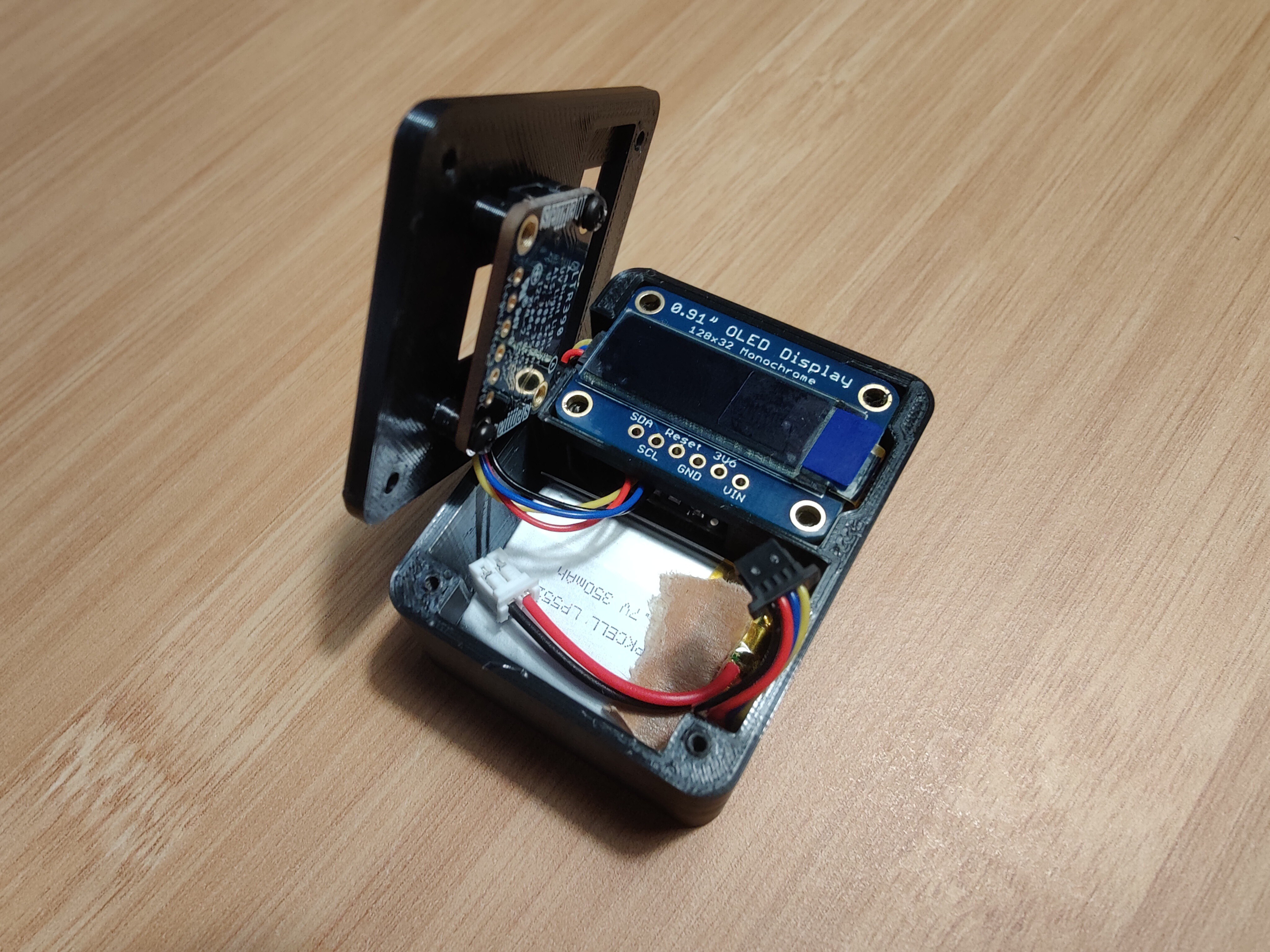
An non-straightforward journey to build a wearable UVI indicator.
Become a Hackaday.io member
Already have an account? Log in.
Just one more thing
To make the experience fit your profile, pick a username and tell us what interests you.
Pick an awesome username
hackaday.io/
Your profile's URL: hackaday.io/username. Max 25 alphanumeric characters.
Pick a few interests
Projects that share your interests
People that share your interests


 sjm4306
 Linus Dillon
 VALENTINE
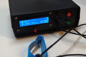
 facelessloser
Fair enuf, been there too.. way past my knock-off time too.
could U please fix the dud link to github?!