-
Measure thrice....
05/20/2023 at 20:07 • 0 commentsThe joke's on me. I've been saying all along that the vents in my house are 12x4 inches. That's true, and I've taken the measurement a couple of times to make sure I didn't fake myself out. Now that the assemblies of fans are ready, it was time to put the first one into a vent cavity. That's a different one from where I have been measuring. It's still 12x4, but there were several irregular protrusions where pieces of the hardwood floor had been cut to make the opening for the vent. There was enough irregularity that it was pretty difficult to get the fan assembly into the vent cavity and then put the register in place between the risers of the fan assembly.
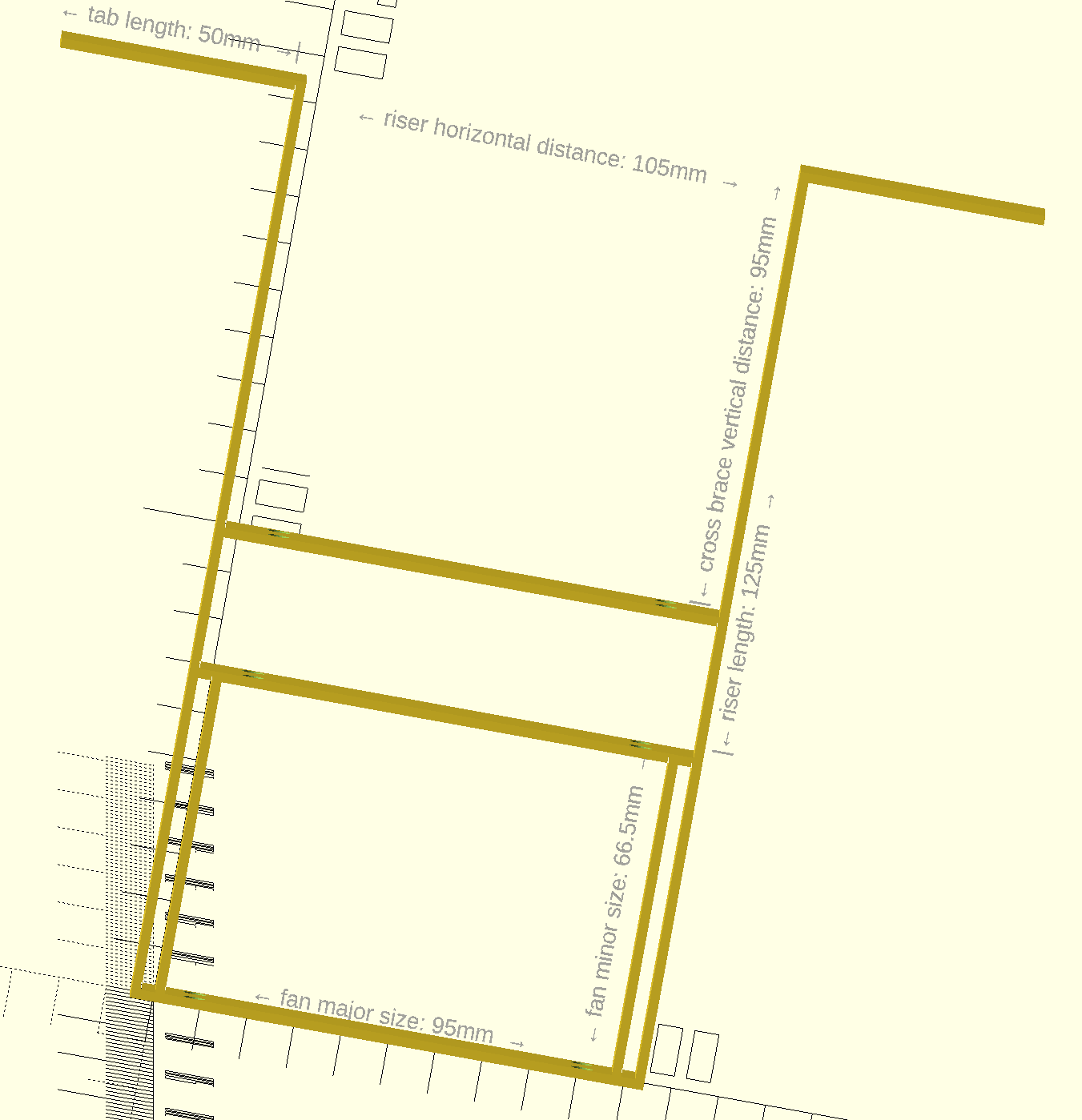
The bracket design for the fans was done parametrically in OpenSCAD, so it was straightforward to make dimensional adjustments. I did have to change my philosophy about it, though. Here's my reference image of the bracket design (the dimensions are intentionally absurd so that the text labels are in the right places and legible).
![]()
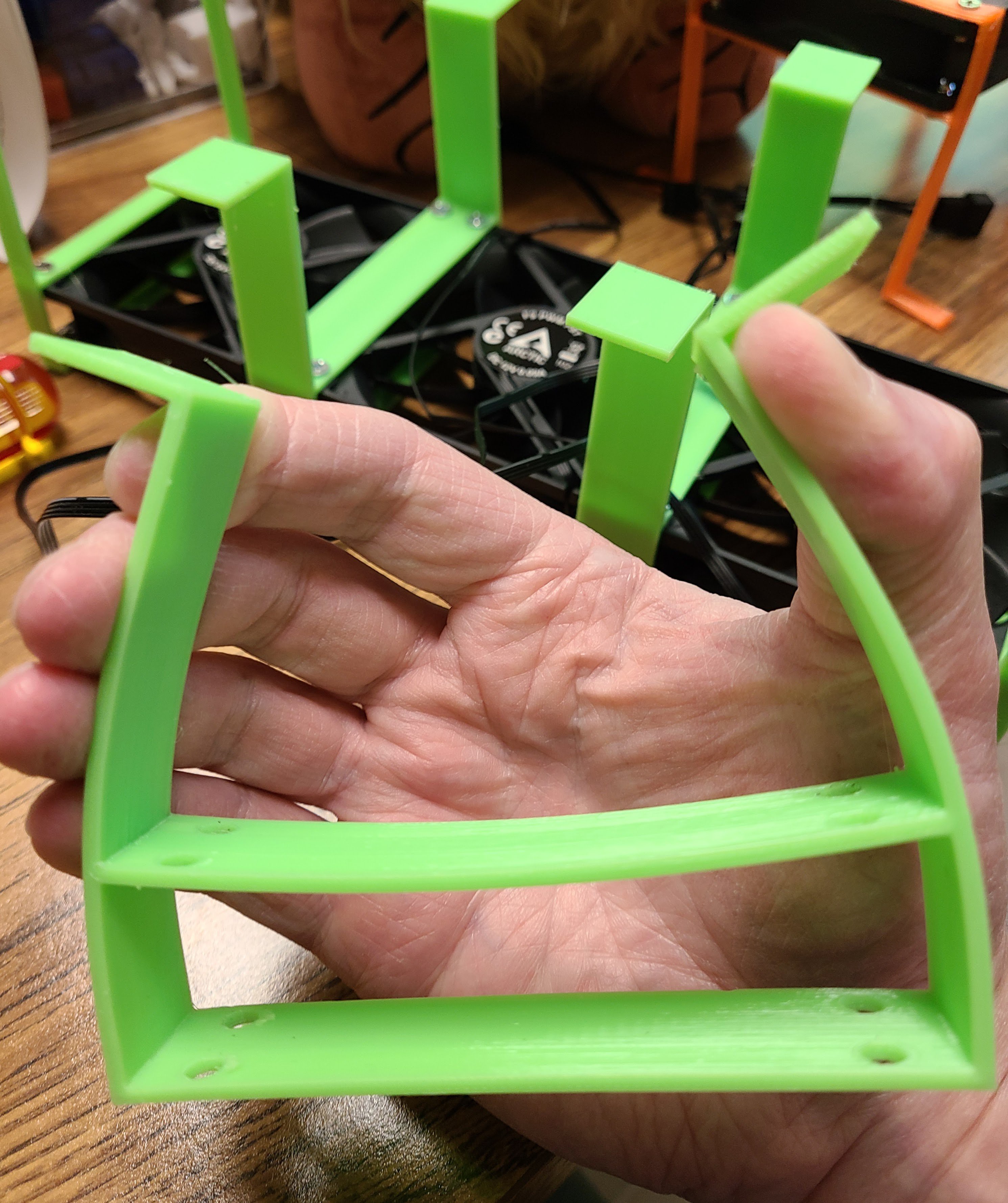
Previously, I had been thinking that I wanted to risers on the bracket to be as close to the walls of the vent cavity as possible, so the register would sit loosely between them. The weight of the register would hold the horizontal tabs in place. My change in thinking is that the riser horizontal distance is now pretty close to the fan major size (in fact, identical). The register now pushes the top of the risers outward while continuing to press down on the horizontal tabs. I printed the brackets in PETG, which has reasonable flexibility, as you can see in the professional demonstration in this picture:
![]()
When you get right down to it, I don't have a tremendous amount of slack anyhow. I'm using 92mm fans. WIth the overhead of the square case holding the fan, it's about 95mm. The thickness that I arbitrarily chose for the thickness of the bracket band is 2mm, giving a total of 99mm (about 3.9 inches). So, yeah: tight.
Things were also reasonably snug in the long dimension, too. I originally used the same brackets on the end fans as I did for connecting two fans side by side. That meant a half of the bracket band width sticking out from each end of the assembly. It still fit into the cavity, though. Since I was going to reprint the brackets I had already made, it was a simple matter to tweak the parameters in the design to make a half-width bracket with single holes for the ends. You can see a couple in the background of the image above.
-
Film at 11
05/17/2023 at 02:43 • 0 commentsI made a short video of the ventbt operation.
This short video demonstates:
- Ventbot powering up and going through its autodetection sequence.
- Turning on the fans in the default ramp-up sequence.
- Turning off the fans in the default ramp-down sequence.
(These were all triggered by me pressing test mode buttons and not by the temperature sensor. I suggest you turn off the audio to avoid the annoyance of background footsteps, paper rustling, clocks ticking, etc.)
-
Brackets
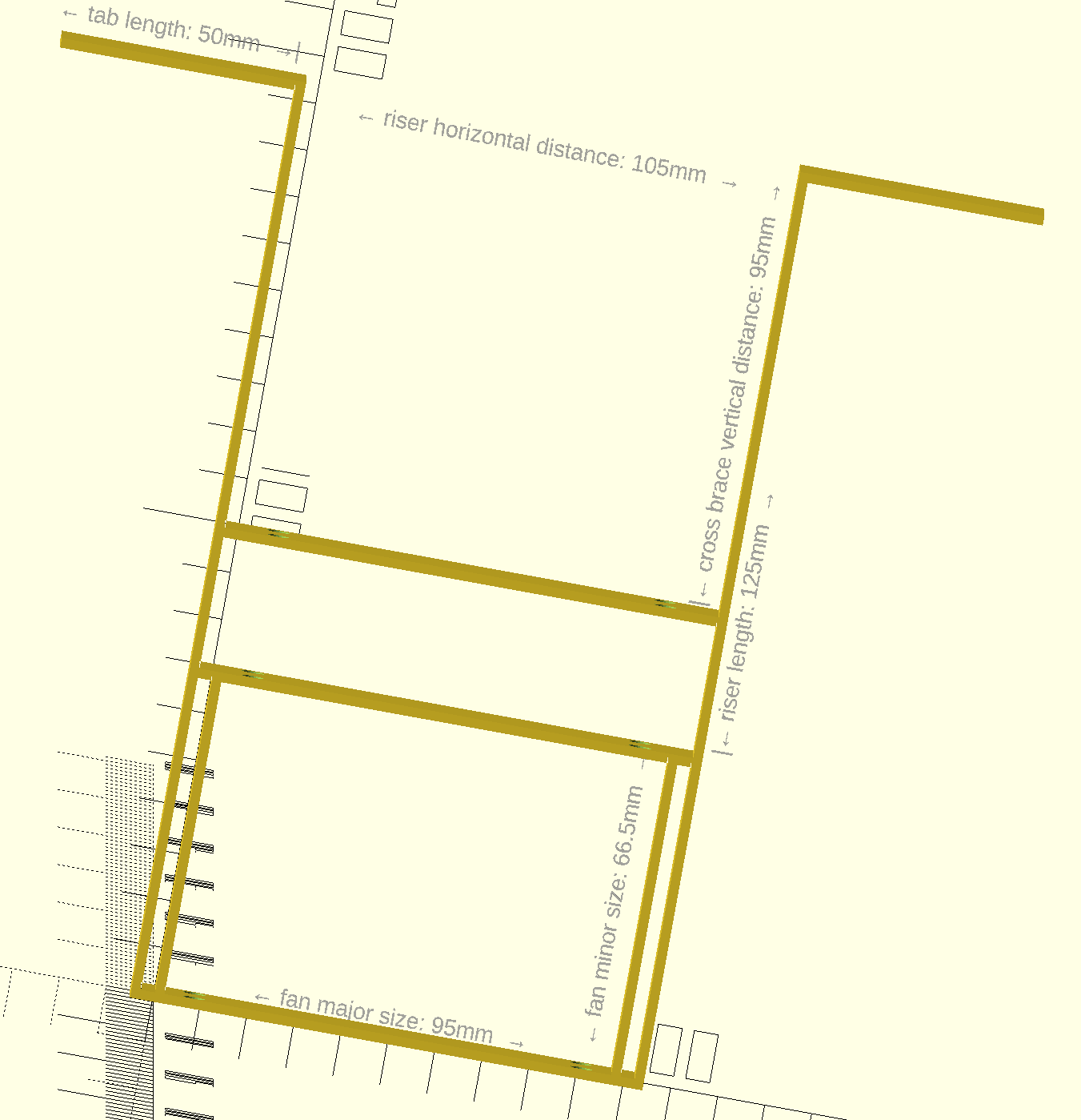
05/17/2023 at 02:40 • 0 commentsI haven't updated this project log for a while, but I have been working on a few things. One thing that I just finished is the design for the brackets to hold the fans themselves. I had a couple iterations of this, but I eventually simplified it to make it less confusing. I designed it in OpenSCAD so that it's easy to change dimensions. The SCAD file is part of the design repository. This image of the reference design (the "reference" preset) has absurd dimensions, but I did it that way so that the labels for the parts would be very visible and in unambiguous locations.
![]()
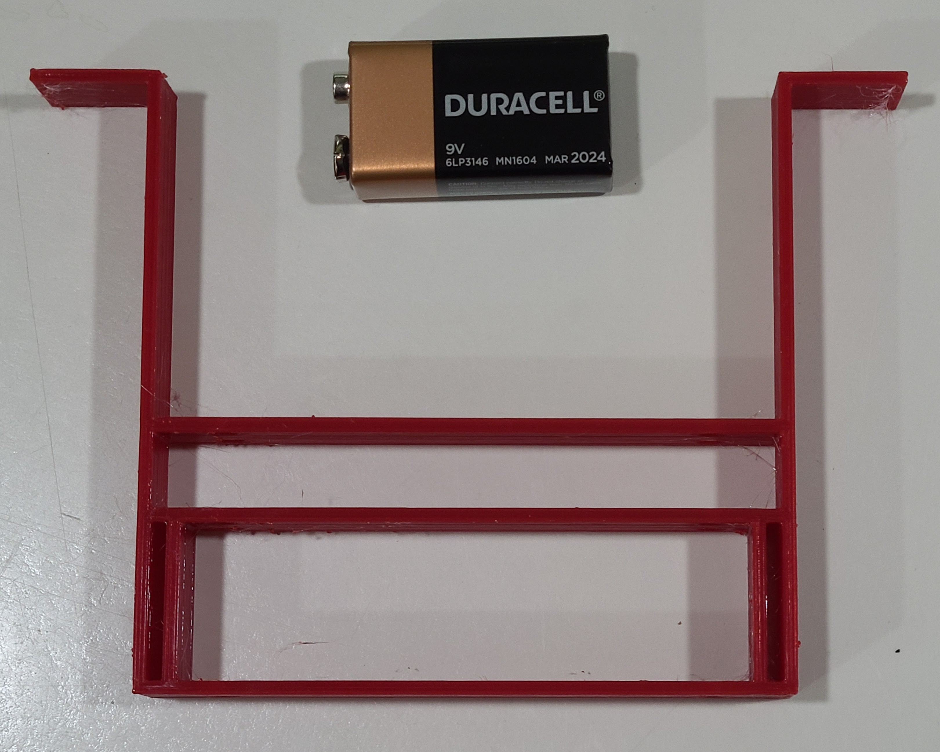
Here's a photo of a more realistically-dimensioned "reference" bracket (the battery is just for scale):
![]()
The bracket design incorporates the following ideas:
- Of course, you can customize any of the dimensions.
- The inner box (the "fan box") at the bottom holds two fans side by side. It's not visible in the above images, but there are holes in the bracket for screws.
- The bracket can either hang from the sides of the vent opening or can stand on the floor of the vent cavity.
- Accordingly, the horizontal tabs (at the top of the images) can be set to point inward or outward.
- The vertical risers can attach to the fan box right at the fan box ends or offset inward or outward.
- There is an optional cross-brace near the middle in the images, for added stability. There are holes in the cross-brace so that you can put a screwdriver through to get at the screws on that side of the fan box.
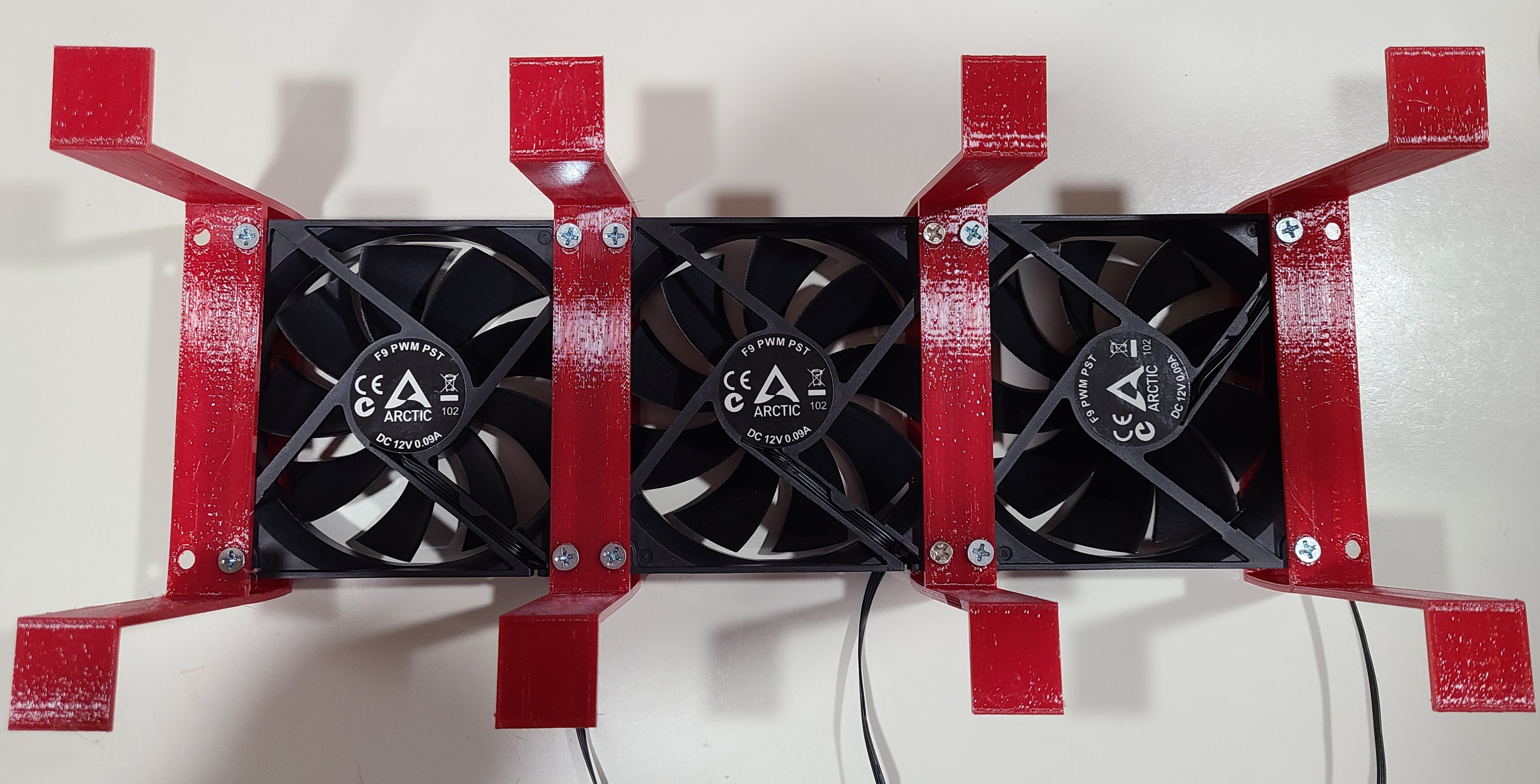
Here's what it looks like with 3 fans (92mm) held together with 4 brackets. (I didn't use a cross-brace.) The brackets on the end are not strictly necessary, but I used them for added stability.
![]()
I printed the brackets with PETG filament. It took a little trial and error to dial in the dimensions.
-
Cases of cases
02/22/2023 at 02:17 • 0 commentsI only plan to use a total of 5 ventbots in my house, but I've printed more than a dozen copies of my custom 3D printed case. That's not including a few more failed prints for various reasons. A few of the extra prints were because of tweaks I made to the design, but most were done to try to get things just right.
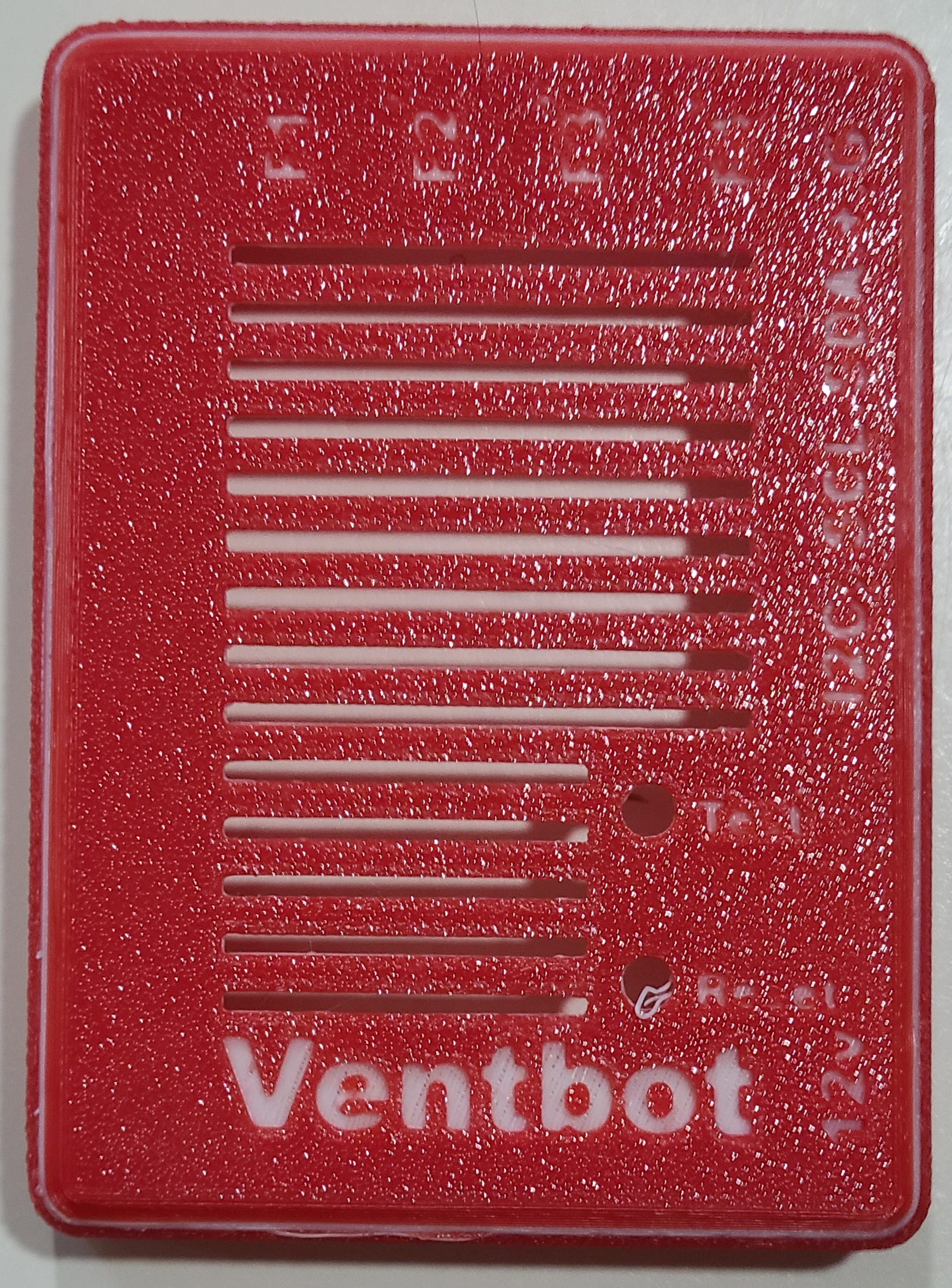
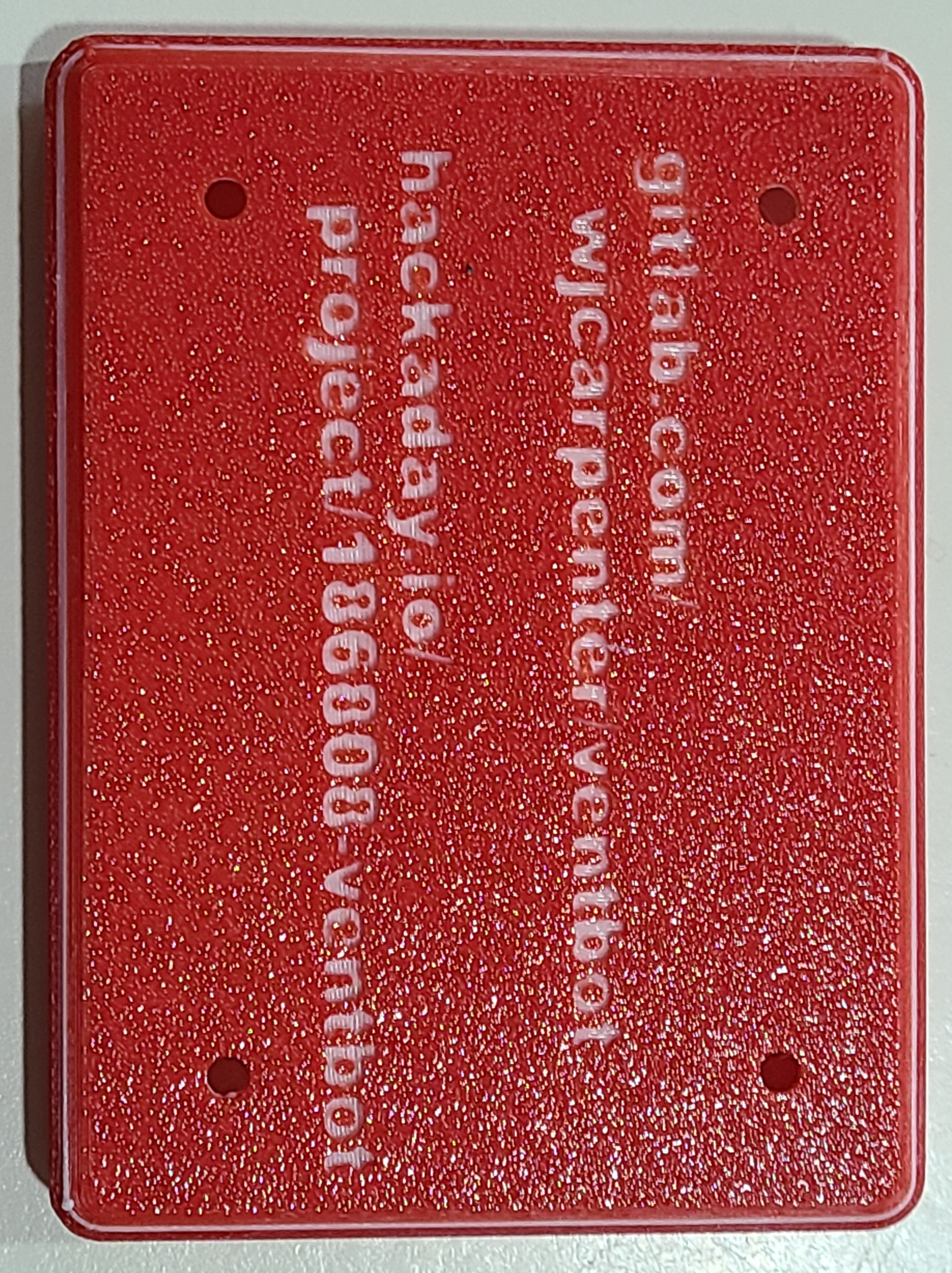
Both the top and the bottom of the enclosure have engraved lettering on them. The bottom just has a couple of URLs pointing to this project. That's a convenience for anyone who comes across one of these gadgets and wonders what the heck it is. The URLs are also silkscreened on the PCB. The top of the enclosure is a little more complicated, with some handy reminders for some of the connections and labels for the holes that lead to the two on-board ESP32 buttons. Getting the lettering to be readable on a 3D printed surface is quite a challenge.
![]()
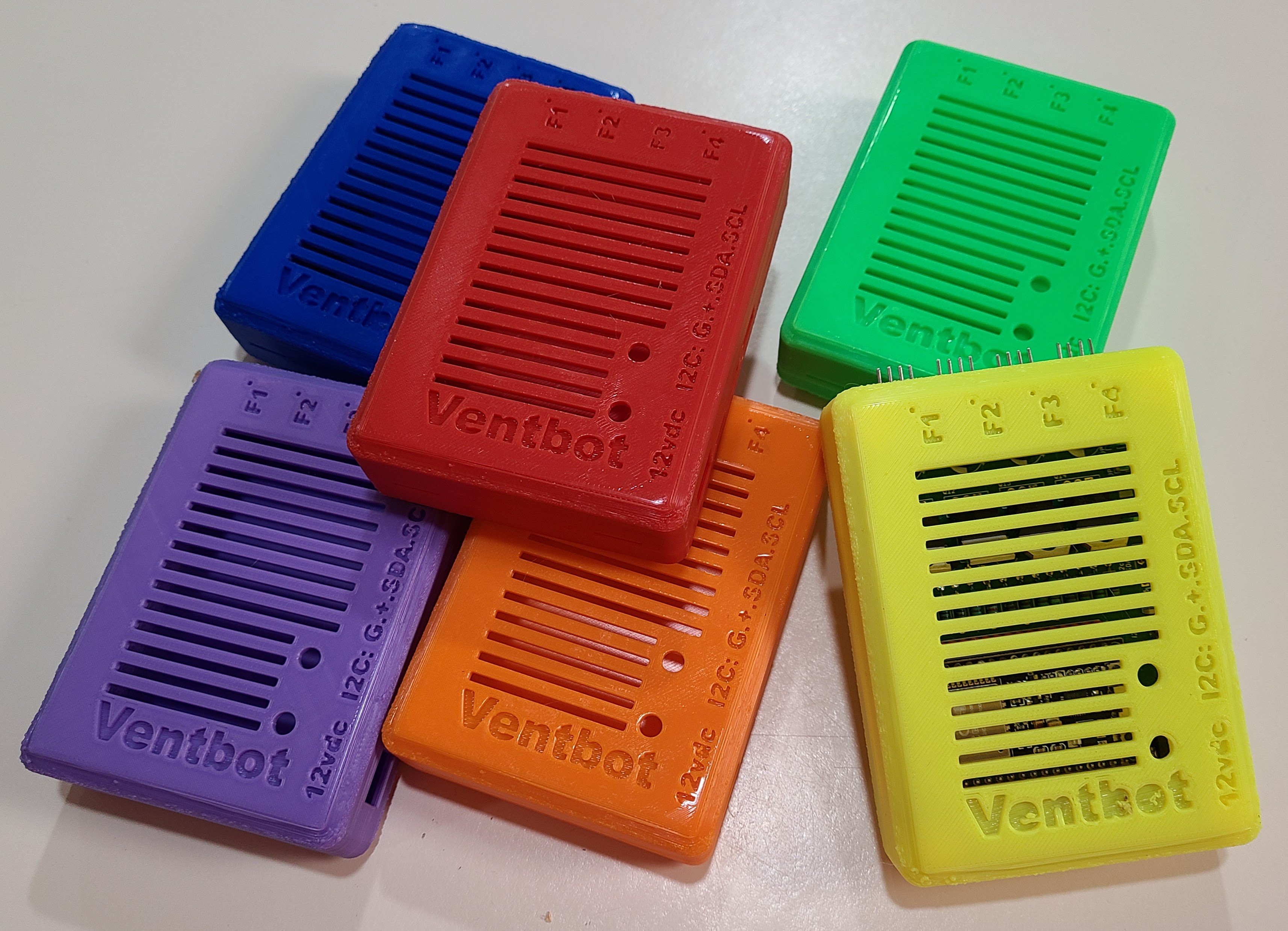
Everyone knows the most common 3D filament is PLA. The ventbots will live inside furnace ventilation ducts. The temperatures of 100F or so is well below any interesting temperature for PLA, but I'm not quite so sure of the long-term stability of it with a lot of thermal cycling. I put one into a vent for a few days and didn't see any degradation, but that's hardly a fair longevity test. Even though I printed my original set of enclosures with a fortified flavor of PLA, I'm recommending that they be printed with PETG instead. So, I've got some of each. The photo above is my original collection (before some design tweaks) of fortified PLA prints, which look pretty nice.
Not all the text on all of the colors is readily readable. The darker the color of the material, the harder it is to read the text. I did some experiments with filament changes during the print. This first one is a red enclosure with a few layers of white for contrast. Because of the simple filament swapping, it also puts a thin white stripe around the outside. For that print, I used a textured bed surface, which causes many tiny points of glare to work against my goal.
![]()
![]()
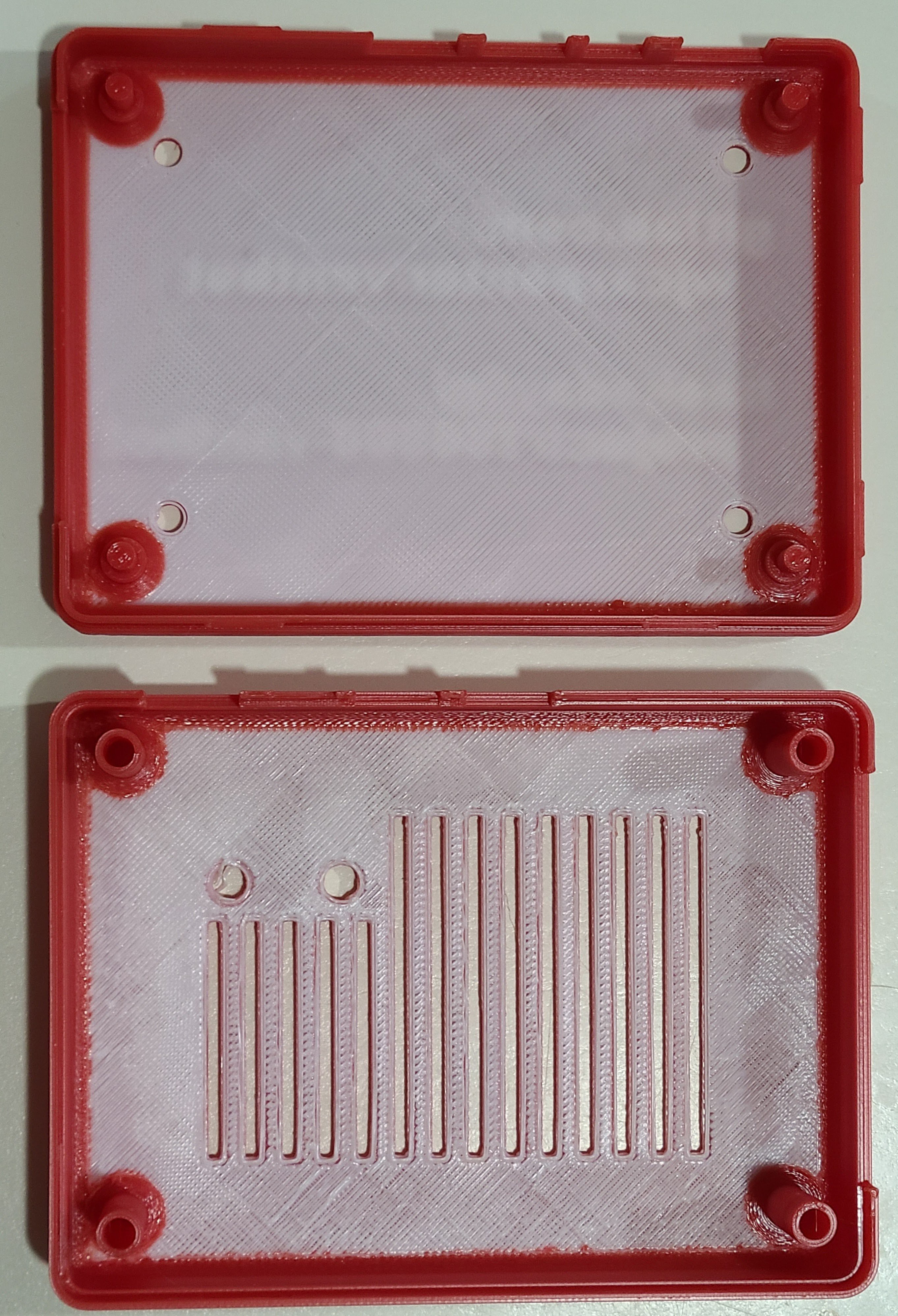
For what it's worth, here's what the inside looks like with this technique.
![]()
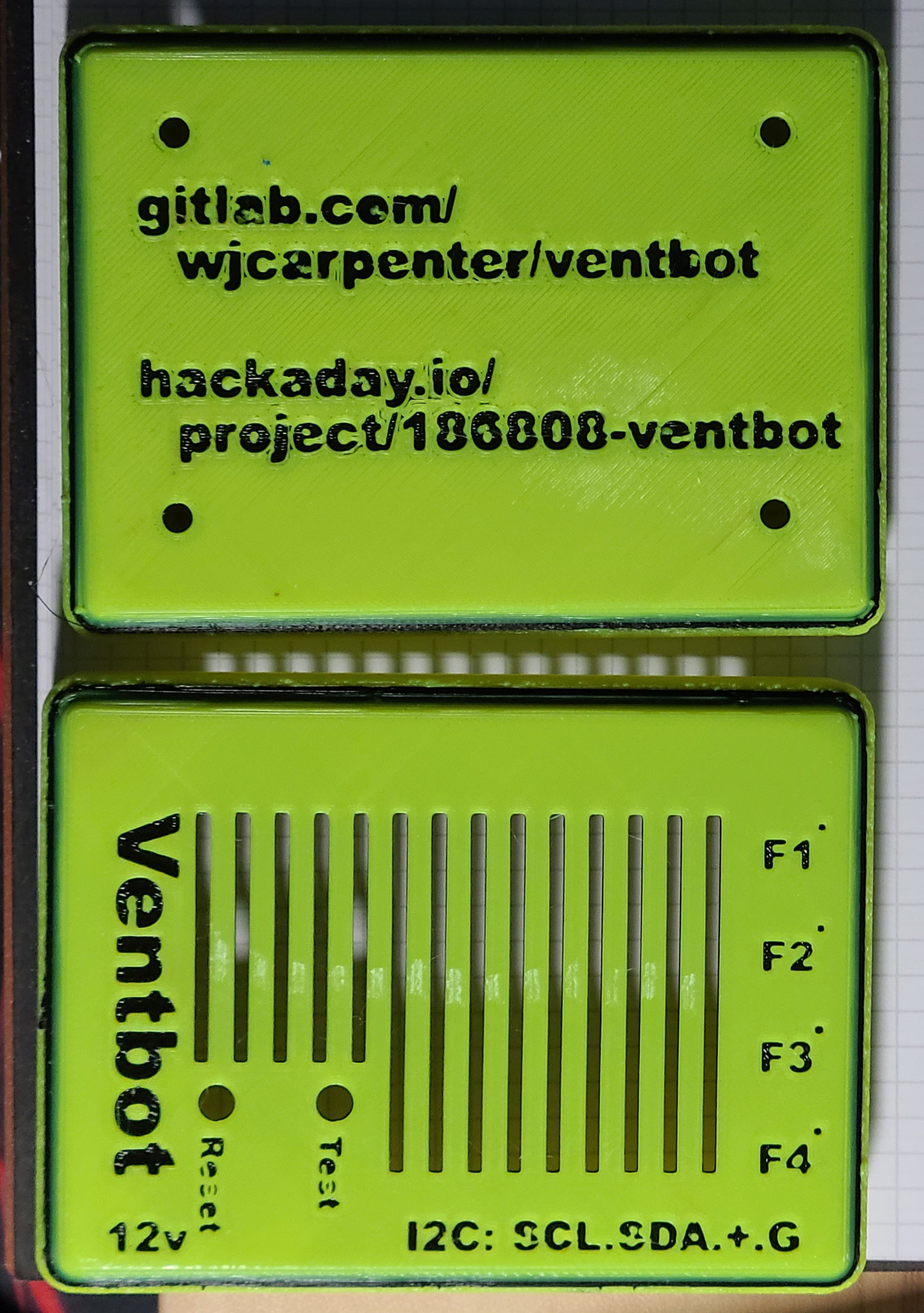
The next images are a similar experiment with PLA, but using a smooth build plate for a yellow enclosure with a few layers of black filament for contrast. That contrast makes those letters very readable, but the outlines of the letters are not especially crisp. I think it looks kind of cool, though.
![]()
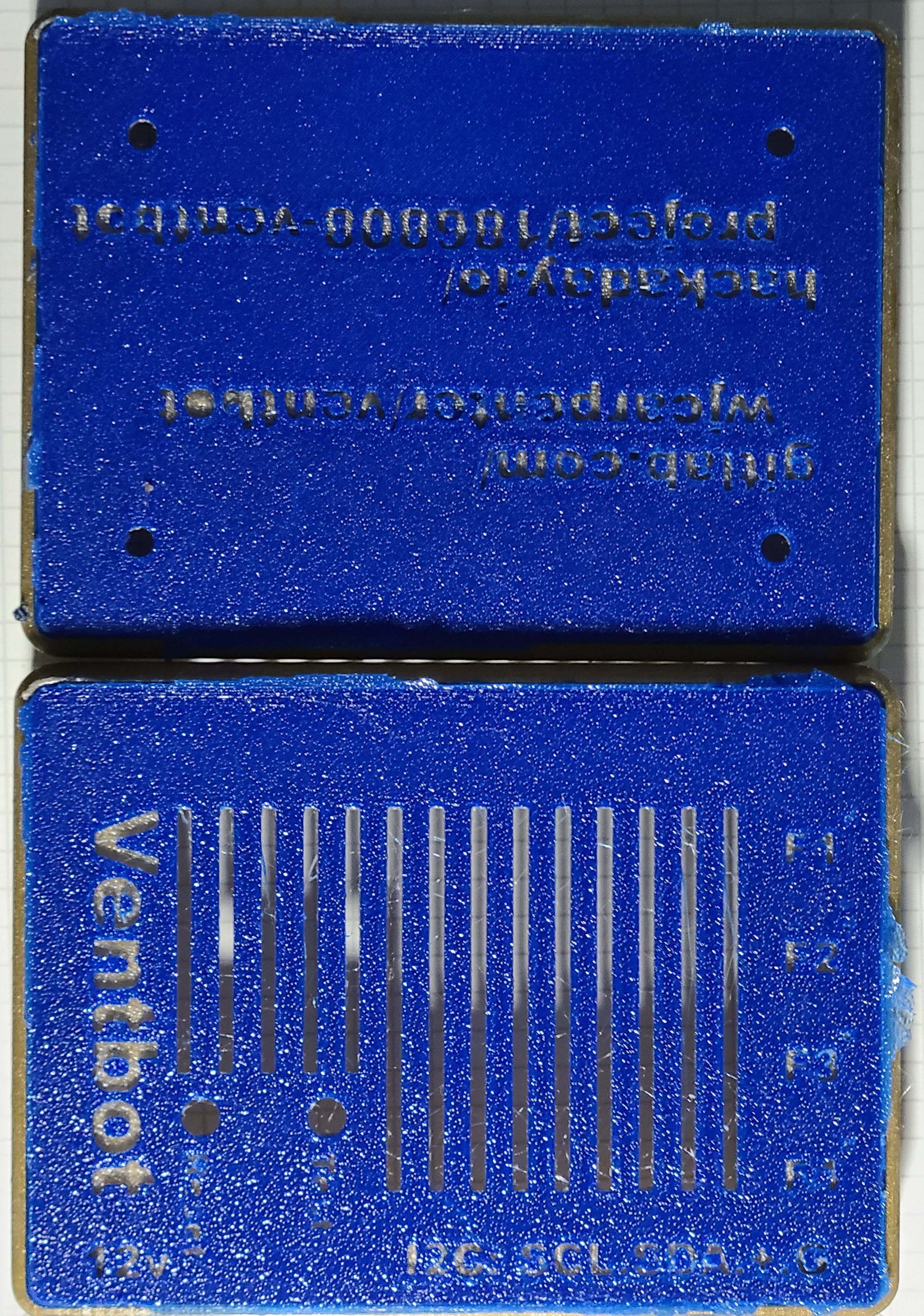
Here is a trial with PETG on a textured build plate. The top and bottom are dark blue, with a contrasting gold layer (I didn't have any black or white PETG filament). Instead of switching back to blue after a few gold layers, I finished the print in gold. You can't see it very well in the pictures, but that gives a box with a blue top and bottom and gold sides all around. The textured surface and the color combinations makes the text pretty hard to read. (The raggedness around the edges is brim material that I didn't bother to clean up very well because I didn't plan to use this copy of the enclosure once I saw the text.)
![]()
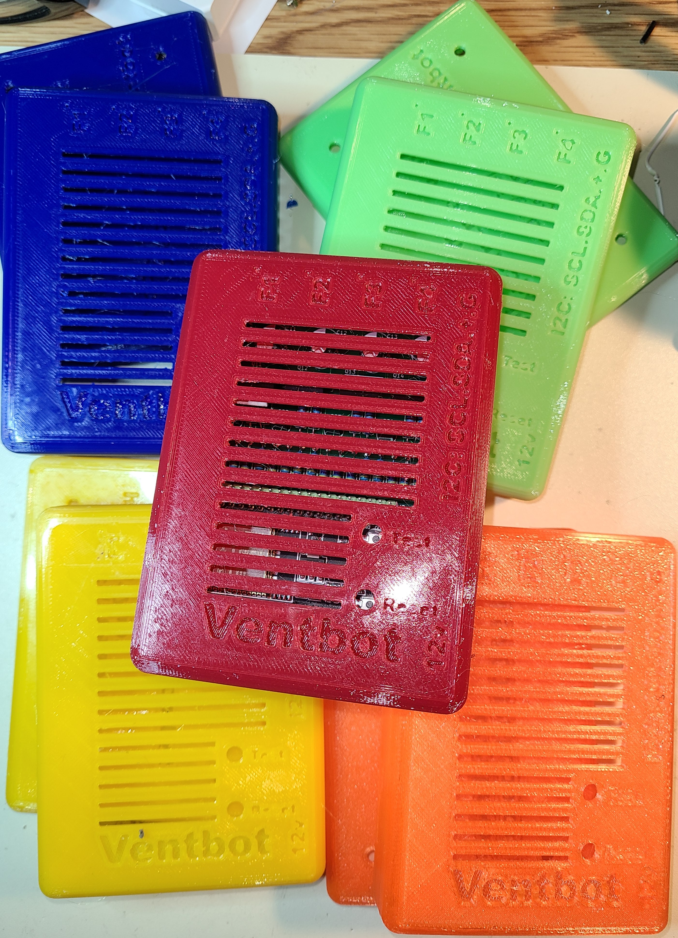
In the end, I printed enclosures I plan to use in a variety of PETG colors with no contrasting layers. After all, I'm going to be shoving these things into a place where they will seldom be seen except by spiders and Darby O'Gill and the little people. Plus, I got tired of experimenting (each print took over 7 hours to complete). PETG tends to be inherently shiny, which makes the lettering harder to read. But, if you hold it at a slight angle to the light, the lettering becomes reasonably clear. All of these were printed on a smooth bed, except for the orange one, which was on a textured bed.
![]()
(I also have some color-changing PLA filament, which goes from orange to yellow at about 81F. That would be kind of interesting if these were going to be in a visible location.)
-
38 pins vs 30 pins
02/20/2023 at 01:10 • 0 commentsI did the whole design based on using the 38 pin ESP DevKitC, though there are a lot of unused pins. I started wondering if someone could use the PCB with a 30 pin ESP DevKitC, with only software changes. The answer is "almost". The pin assignments in the software and in the physical PCB layout are in this project log entry: ESP32 pin assignments
My assumption is that any of the software-controlled inputs and outputs could be switch to another pin, modulo things like "input only" pins. I can't change things that aren't controlled by software: Vin 5v, 3.3v output, and ground pins. Many, but not all, of the signal pins line up nicely in the two footprints if you slide the 30 pin device down one notch. That is, pin 1 of the 30 pin device is placed in position pin 2 of the PCB footprint.
The 38 pin layout looks like this:
1  3.3v         38 gnd
----------------------------
2  reset*       37 f4-pwr*
3               36 i2c-scl*
4               35
5               34
6               33 i2c-sda*
7               32
8               31 f4-tach**
9   f1-tach*    30 f4-pwm**
10  f2-tach*    29
11  f3-tach*    28 f2-pwm**
12  f1-pwr*     27 f1-pwm**
13  f3-pwr*     26
14  gnd*        25
15  f2-pwr      24
16              23 f3-pwm
---------------------------
17              22
18              21
19  Vin 5v      20
In that list, signals marked with a single asterisk means that they show up in the same GPIO on the (adjusted) position on the 30 pin device. (It can be a little confusing because not all of the GPIOs how up in the same relative positions. It's the GPIOs that are of interest.) Signals marked with 2 asterisks mean the corresponding pin isn't the same, but the signal can still be accommodated with a software re-arrangement. Signals with no asterisk means that something extra has to be done.
Here's the corresponding (adjusted) 30 pin layout:
1  reset        30 f4-pwr
2               29 i2c-scl
3               28
4               27
5               26 i2c-sda
6               25
7               24 change from f4-pwm to f4-tach
8  f1-tach      23 same as 29 (GPIO 5), as f4-pwm
9  f2-tach      22
10 f3-tach      21 change from f1-pwm to f2-pwm
11 f1-pwr       20 same as 26 (GPIO 4), as f1-pwm
12 f3-pwr       19
13 gnd          18
14 gnd          17
15 Vin 5v       16 3.3v
Here are the modifications needed to make this work:
- Software change to move GPIO signals as indicated
- Jumper from PCB pin 19 to PCB pin 16 for Vin 5v
- Special handling for f2-pwr and f3-pwm, described below.
The special handling for f2-pwr and f3-pwm is required because the corresponding pin on the 30 pin device is ground or 3.3v output. There's no way around it other than severing those signals and running a new f2-pwr and f3-pwm signals.
Luckily, there is an unrelated PCB option that can come to the rescue for f3-pwm. The signals for f2-pwm, f3-pwm, f4-pwm, f2-pwr, f3-pwr, and f4-pwr are routed to 3-pin jumper options. On the v4 board, there is a trace connecting pin 1 and pin 2 of each of those jumper options since that's the behavior that is usually wanted. That trace is on the top side of the board, not clearly visible under the solder mask and silk screen.
Unfortunately, the same jumper option trick can't be used for re-routing f2-pwr. The f2-pwr signal is a digital signal controlling a MOSFET transistor, and it's the output of that MOSFET that goes through the jumper option. There is an only semi-ugly hack that we can use. The digital signal controlling the MOSFET for f2-pwr passes through resistor R42. Instead of soldering both ends of that resistor to the PCB, solder only the lead nearer the MOSFET. The other lead, which would normally be soldered to a pad nearer the ESP32, can be left unsoldered as an attachment point for a jumper wire.
The complete fix would be:
- Software change to move f2-pwr and f3-pwm from current pins to some other available GPIO pins.
- Jumper from PCB pin 23 to PCB pin 1 to provide 3.3v output where needed.
- Cut the trace between pins 1 and 2 of PCB JP23 and JP12.
- Jumper between pin 2 of PCB JP23 to the new f3-pwm pin chosen above.
- Jumper the near end of R42 to the new f2-pwr pin chosen above.
I haven't tested this, but it should all work out unless I have made a mistake. Aside from software changes, which should be a trivial ESPHome config file edit, it's just 1 cut trace, one lifted resistor lead, and two "white wire" jumpers, which is not too bad. If I had been thinking about this from the beginning, I could have made the special handling of f2-pwr and f3-pwm unnecessary. Oh, well.
-
Heatsink musings
01/21/2023 at 19:06 • 0 commentsI said earlier that the 7805 got warm but not hot. That was true of my breadboard experiment. When I put one on the actual PCB, it was sometimes warm and sometimes really, really warm. I don't know what temperature it reached, but it was a bit uncomfortable to the touch. It was still possible to keep touching it with my finger indefinitely. I'm not sure how the 3D printed case will feel about that permanent source of heat after a few months.
I'm not sure why there was a difference on the breadboard compared to the PCB (it happens to be exactly the same 7805 device). I'm thinking about ways to reduce the ESP32 power draw (maybe by reducing the clock frequency or whatever other tricks I can come up with while staying in ESPHome), but I will probably add a heatsink to the BOM.
Meanwhile, I have been exploring homebrew heatsink stuff. Here is what I have found so far:
- The hole in the tab of the TO-220 package is 3.7mm +/- 0.1mm.
- 3.7mm +/- 0.1mm works out to 0.1417 to 0.1496 inches, or about mid-way between 9/64 and 5/32 inches.
- JEDEC (registration required) gives the dimensions in inches, min 0.139, max 0.161.
- I don't know how closely manufacturers adhere to any of those specifications.
- I found that an M4 screw just barely fits into the devices that I have. It doesn't slide in and out, but it can be easily threaded into the hole. It's not snug enough that it doesn't need a nut.
- In North America, the standard screw for holding an electrical wall plate in place is size #6-32. The major diameter for #6-32 machine screws is 0.138 inches / 3.505mm. These are readily available in the US. I've got about 5 billion in various places in my junk box. Because of the way they are used, you usually find them without matching nuts, though the nuts are also readily available at any hardware store.
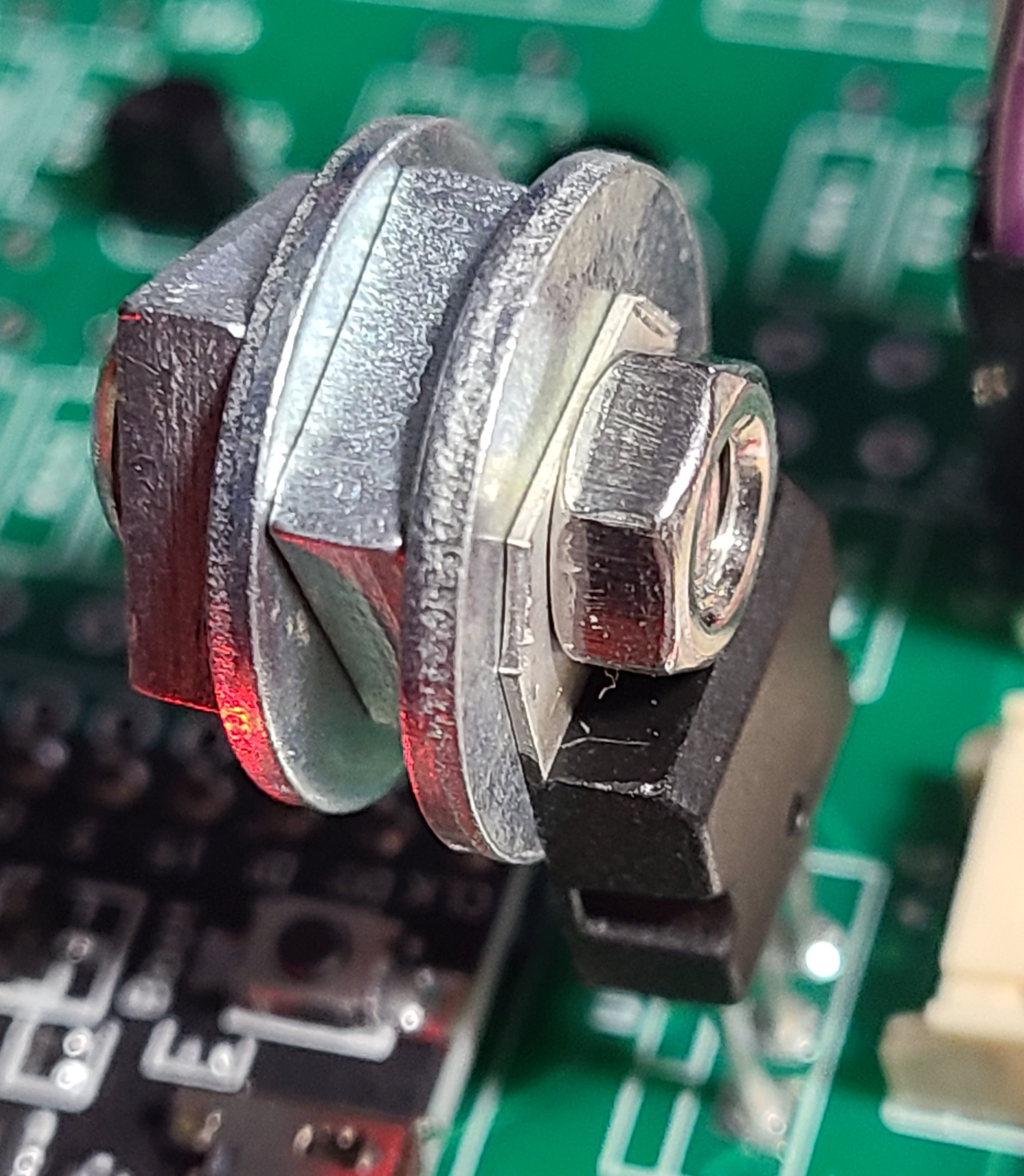
I was able to cobble together a makeshift heat sink using loose nuts and washers from the junk box. The only (tiny) challenge was finding a nut that was small enough in outer diameter to avoid the body of the TO-220. I wanted to insert the screw from the back side of the TO-220 so that any excess would point up and away from the ESP32 if I leaned the voltage regulator backwards to reduce its height, and also because any of the nuts and washers I used would also interfere with that body.
Here's a picture of my Frankenheatsink (M4 screw and nut, loose-fitting junk draw nuts and washers):
![]()
So far, it's staying just warm and not getting really, really warm.
-
A powerful follow-up
01/14/2023 at 20:51 • 0 commentsReplacing the AMS1117 regulators on the ESP32 modules was a wash-out. I had two board with what I hoped were just burned out AMS1117 regulators. On one board, replacing it made no detectable difference. On the other board, I heard some snap-crackle-pop for a few seconds, and then smoke appeared. So, I'm giving up on that idea. I've got a small quantity of AMS1117 chips for some future project.
My 7805 regulators arrived. I've breadboarded one of them to power an ESP32 through the 5v pin. The ESP32 is running the ventbot firmware. Except for not connecting the BMP280 over I2C, this is exactly what will be running, so the current draw should be pretty close. I've already had it running for 15 minutes or so. With my finger, I can feel some warmth on the 7805, but nobody would reasonably call it "hot". So, I think I won't need to worry about a heatsink for the 7805 for this project. Yay!
-
PCB 3rd iteration, with more DFM
01/12/2023 at 20:09 • 0 commentsI made the decision to revise the PCB again, to correct one definite (non-fatal) mistake and another arguable mistake. At the same time, I made a number of smaller changes in the name of "design for manufacturability" (DFM). In this case, the "manufacturer" is mostly me. If someone else builds some of these, they will also probably be a hobbyist. They'll be sourcing parts in small quantities, maybe taking what they can find or using what they have on hand. They'll be doing assembly in a dungeon-like work area that doesn't want to have computer equipment and lots of paperwork strewn about. OK, I'm really talking about me.
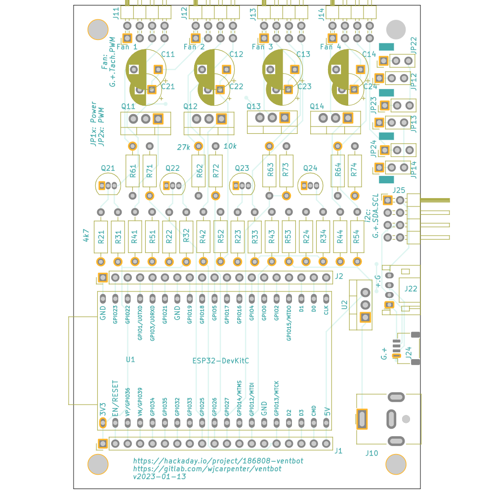
![]()
Here are the changes I made:
- Added the footprint for the 7805 (U2). I placed it so it wouldn't block the USB connector on the ESP32 module. There should still be enough room for the 7805 to "lean back" a bit if it doesn't need a heatsink.
- Corrected the pin ordering for the JST-PH connector (J22). This was backwards in the first two iterations of the board, so you couldn't directly use it with STEMMA or Grove components. I added a bit of marking on the silkscreen so that it's clear which pin is which for the wiring for it and the JST-SH (J24) connector.
- I changed the footprint of the other I2C connector (J25) from two separate (but conveniently spaced) 1x4 pin headers to a single 2x4 right angle pin header. That makes it more obvious what's going on, and someone could still use separate straight-through pin headers if they wanted to.
- Along the same lines, I changed the footprints of the fan connectors (J11, J12, J13, J14) to be those same 2x4 right-angle pin headers. To use those, you have to snip off the bottom row of horizontal pins, but the pad spacing and physical dimensions are otherwise compatible with the official friction-fit fan connectors. Someone could still choose to use either vertical insertion or right-angle versions of those.
- For the power and PWM option jumpers (JP12, JP13, JP14, JP22, JP23, JP24), I have previously populated boards both ways: with a 3-pin header and jumpers, and with wires soldered across pins 1-2. Given that the choice will almost always be connecting pins 1-2 for all six options, I wanted to simplify that for the common case. I left the footprint as a 3-pin header, but I put a trace between pins 1-2 on the front of the board for all six options. If someone wants to select pins 2-3, they can cut that trace and then join pins 2-3 with either a jumper or a soldered wire.
- I added some text to the silkscreen as a reminder of which option jumpers control power sharing and which control PWM sharing. Unfortunately, there wasn't room near those footprints, so it's all the way across the board. Tolerable.
- Most of the resistor values were not critical. I changed the 100 ohm current limiting resistors to 4.7k ohms. That reduced the number of distinct resistor values from 4 to 3.
- One of the resistor values was 27.4k ohms. I had copied that value from a reference design. 27.4k is not a standard value, and I had been using 27k when assembling boards. I formalized that by changing the design to 27k ohms.
- I moved some resistor placements around so that the one long row of resistors is now all 4.7k values. That should eliminate some opportunities for making a mistake. That made the R1x resistors appear out of sequence, so I changes their references to the previously unused R4x series.
- I added reminders of values for the various resistors on the silkscreen. That matters most for the two values that are not 4.7k.
- The redone trace routing conveniently allowed me to extend all the way to the edge of the PCB the keepout area for the ESP32 antenna position. I still don't know how much difference that makes, but I have done my duty.
- I added a redundant footprint for the capacitors. The second footprint has a closer lead spacing, which I think is more common these days. Depending on the capacitors you actually have, you can pick whichever footprint gives the best physical fit.
-
Puff the magic dragon smoke
01/10/2023 at 02:32 • 0 commentsWhile putting one of my assembled boards through its paces, smoke started coming out of the grill vents in the case. I quickly opened it up and was able to definitively see that the smoke came out of the ESP32 module's on-board voltage regulator. It's an AMS1117. I've come to the conclusion that asking it to drop 12v input to 3.3v is just too much heat to be dissipated. (I've also since read some unkind words about the part.) I allow for the possibility that the ESP32 modules I have might be tainted by supply chain counterfeiting problems, but I don't know that in any concrete way; it's just generic paranoia.
The voltage regulator is a surface-mounted SOT-223 package (3 terminals plus tab). I've ordered some replacements and will try my hand at repairing the ESP32 module. However, that's more or less a tangent, just to see if I can do it. Who's to say the replacements won't also blow at some point? I don't want that puff of smoke coming out in the middle of the night. Also, I don't know if the blown voltage regulators will have led to catastrophic damage to other things on the module, including possibly the ESP32 itself.
So, what to do about this? I want to continue powering the board with a single power supply. The fans want to run at 12v, so the 12vdc input seems like it must stay.
I'm thinking of adding a 7805 regulator to the board to feed the 5v input of the ESP32 module. That will still have to dissipate the heat in getting from 12v to 3.3v, but:
- it'll be two devices doing it instead of one
- the 7805 will be separate from the ESP32 module, and only 3 pins, so simpler to replace
- if necessary, I can add a heatsink to the 7805
I'm hoping to get away without a heatsink. The ESP32 will probably run at 250mA or so. The typical application circuit puts capacitors on both the input and output voltages. I hope to be able to avoid that because the 5v output will be feeding into the ESP32 on-board regulator. I'm not worried about power consumption, per se, so the only worry I have is about the need for a heatsink.
Another possibility would be to use a switching regulator, which should reduce the dissipation into heat. There are some that are pretty cheap as standalone modules, but I don't want to end up with a separate board or redesigning my board to be much larger. CUI Devices makes a series of switching regulators in a 3-pin package, and I think there are other manufacturers of similar devices. The idea is that they can be a direct replacement for a 7805 on a PCB. I could either feed that into the ESP32 on-board regulator use a 3.3v regulator to directly feed the Vcc pin of the ESP32. If I did the latter, I would probably have to be more careful about the capacitors. It would also be a design-time decision instead of an assembly-time decision.
OK, I've decided. I'm going to do another revision of the PCB to add a footprint for a 7805 and feed the output of that to the 5v pin of the ESP32 module. No capacitors. If someone wants to feed the 12v directly to the ESP32 on-board regulator, they can just jumper the Vin and Vout pads together. Or, they can use a 7805 or one of the pin-compatible switching regulators to drop the voltage to 5v. They can also make a late-binding decision about whether they need a heatsink for the 7805. (It turned out that I didn't have a 7805 on hand, but I will have some soon. I'll do some breadboard experiments to see how warm it actually gets when powering the ESP32.)
-
The enclosure with YAPP_Box
01/02/2023 at 02:50 • 0 commentsI started fiddling around with OpenSCAD to make a custom enclosure for this project. I did what I thought were some reasonably clever things with the base on which the PCB would rest (3D-printed stand-off with threads and matching nuts ... yummy!) However, when it came time to create the top of the enclosure and figure out a way to fasten it together, I came across mrWheel's YAPP_Box project. It was so far ahead of what I was tinkering with that I set my custom enclosure aside and started working with YAPP_Box.
The way YAPP_Box expects you to work is to start with a template of settings and then reference a generator module to actually create the enclosure based on those settings. You could just measure locations on a board with calipers or even a ruler, but I did my board design in KiCad and was able to get precise footprint numbers from property sheets in KiCad. The only thing I actually had to measure was the Z height of a populated board (both front and back), and those did not need much precision.
Just in case I later revise the PCB, I created a bunch of local variable with numbers expressed in KiCad coordinates, and then I set the parameter values for YAPP_Box mostly in terms of those KiCad variables. For things like text labels and grillwork, which didn't correspond to anything on the PCB, I used a combination of measuring, educated guessing, and trial and error. OpenSCAD is a great tool for that kind of iteration since the preview mode is really, really fast at showing what any changes look like. It was a little challenging to keep translating KiCad's idea of coordinate systems to the multiple different YAPP_Box orientations, but, again, OpenSCAD's rapid previewing was very helpful for keeping things going in the right directions.
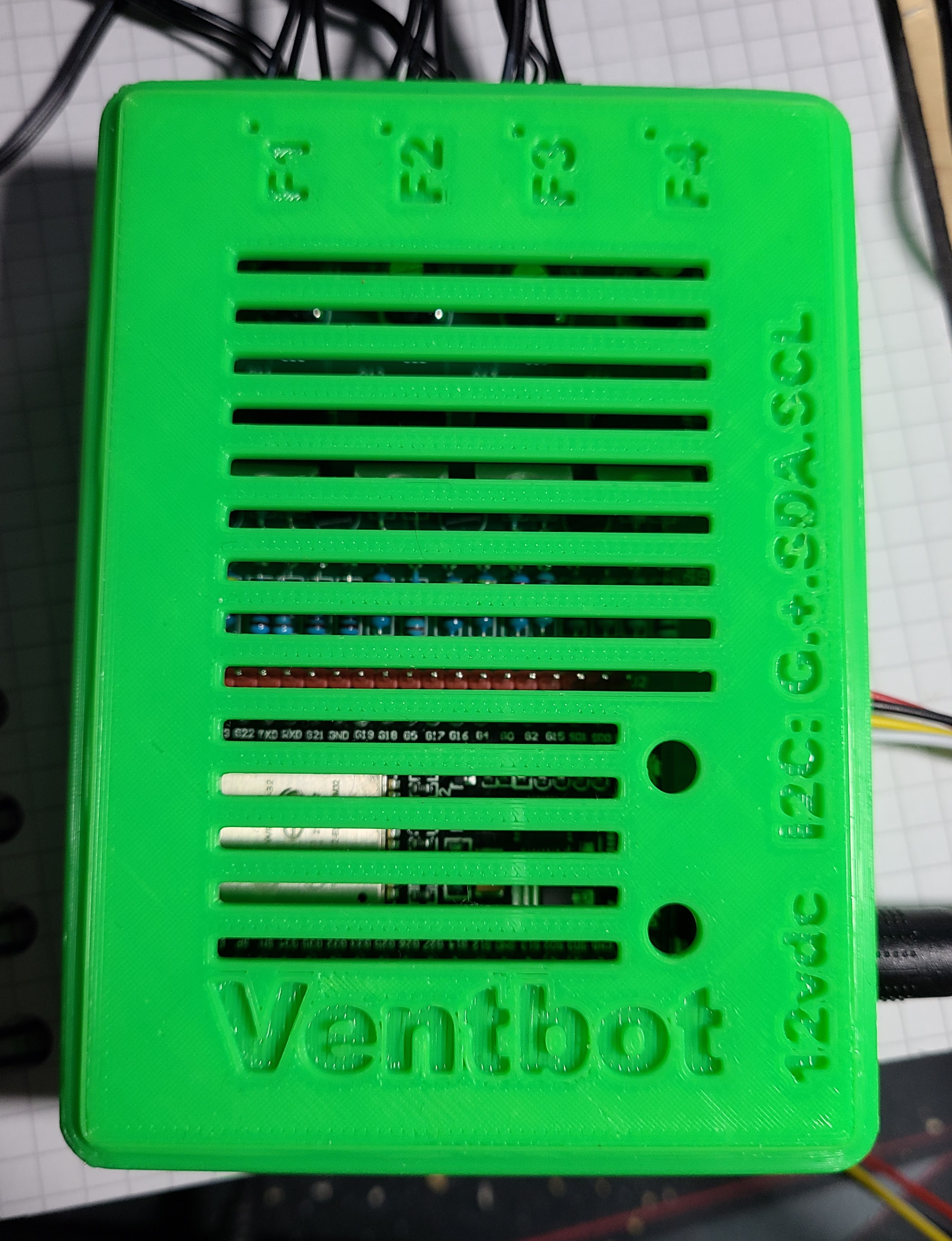
In the end, I made cut-outs on two sides for fan connectors, power connector, and I2C connectors (for the temperature sensor). I tried putting text labels for those things on the sides as well, but it came out looking pretty awful when 3D-printed. Instead, I put all of the text on the top and bottom surfaces. I had to go with rather large Arial Black typeface in bold to get reasonable looking text. YAPP_Box text is done an engraving, so you are mostly depending on shadows to make it visible. Lighter colors work better for that, though these things will be shut up inside furnace vents for the long term.
![]()
On the top, in addition to some text, I also put some grillwork. I don't think it's needed for ventilation, but it was easy to do and looks pretty nice. I also put a couple of small holes to allow pushing the ESP32 buttons when the enclosure is snapped shut. A thin TORX screwdriver is good for that since the flat nose helps you find and press the buttons. (One of the buttons is the reset button, which obvious behavior. The other button is configured in the firmware to let you temporarily toggle the fans on or off for testing. You can do a similar thing with Home Assistant integration.)
![]()
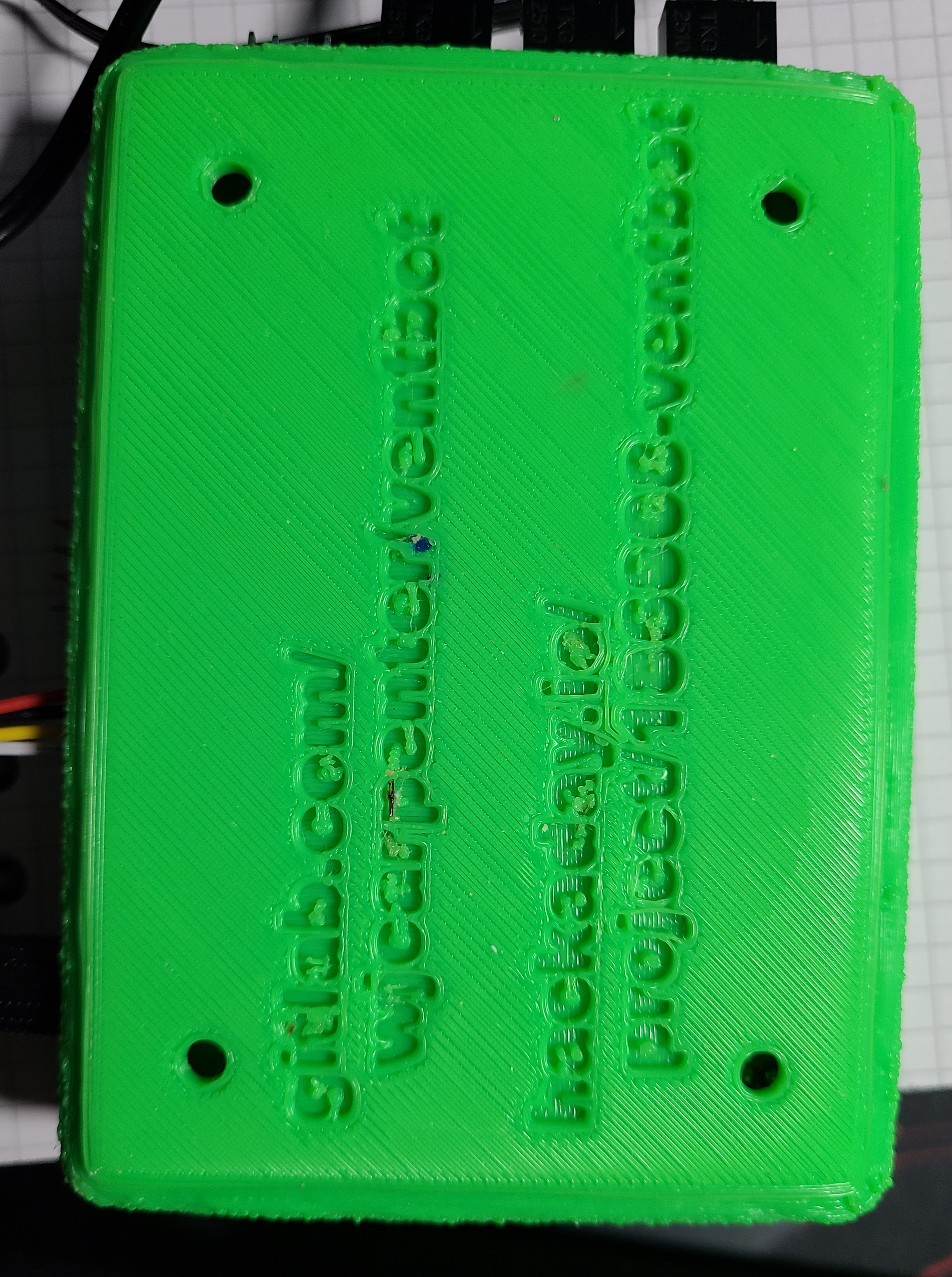
On the bottom of the enclosure, I wrote the URLs for this Hackaday project and the gitlab repo where the design files live. I don't think I am likely to ever lose track of that information, but I know I often lose track of that sort of thing after a couple of years on equipment and components I get from random sources. The URLs on the case are just in case somebody like me builds one and then loses track of me. (The URLs are also silk-screened on the PCB, but that's the kind of thing I might forget to look at after a couple of years.)
There are some "poke holes" in the bottom to help get the PCB back out of the enclosure. I wrecked a couple of trial iterations of the base by prying the board back out with a tool. With the poke holes, you jam that same TORX screwdriver in and push the PCB up from underneath.
Ventbot: warm side cool, cool side warm
A DIY register booster project to even out the temps around my home.
 WJCarpenter