 Lithium ION
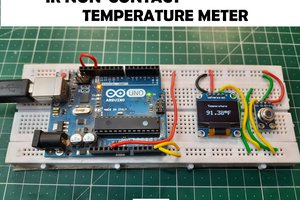
I made a project using non-contact temperature sensor in past, and in this tutorial to reduce the overall display cost, I had interfaced the sensor with 4-digit 7 segment display. The basic idea of measuring temperature remains the same. Just make sure to read the “non-contact temperature sensor using Arduino and mlx90614” to get a brief introduction about calibration components used. This project is sponsored by PCBWAY.com
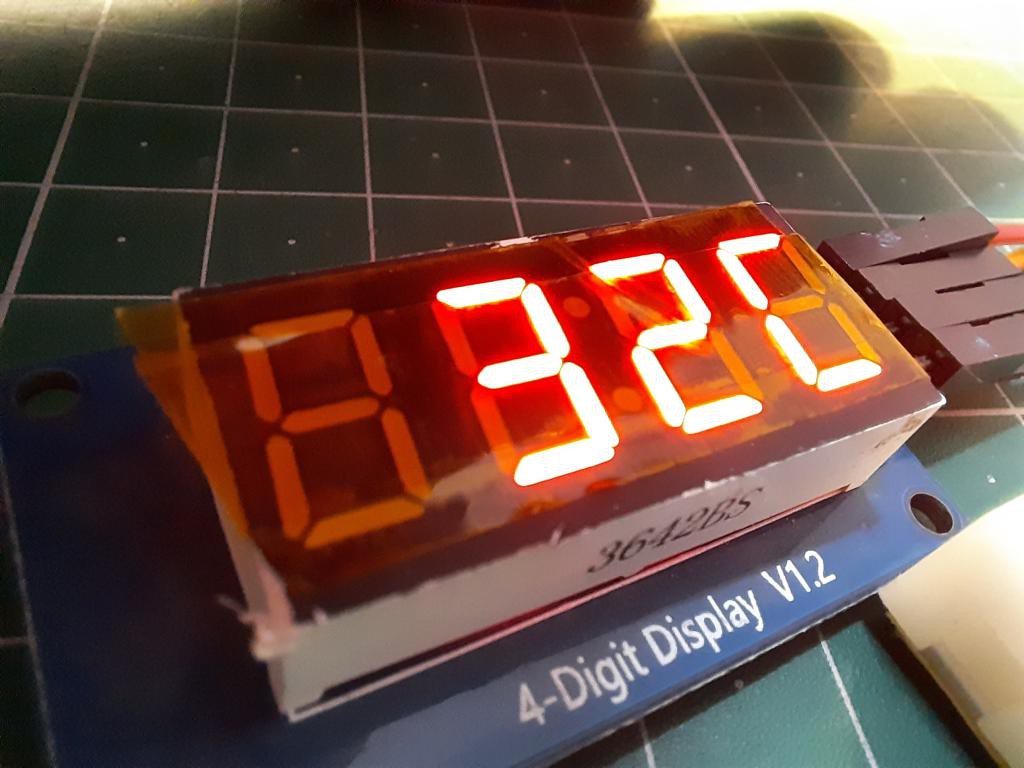
TM1637 display and controller:
This 4-digit display is controlled by an integrated circuit named as TM1637 developed by titan microelectronics. Here I have some info directly from datasheet- TM1637 is a kind of LED (light-emitting diode display) drive control special circuit with keyboard scan interface and it's internally integrated with MCU digital interface, data latch, LED high pressure drive and keyboard scan. This product is in DIP20/SOP20 package type with excellent performance and high quality, which is mainly applicable to the display drive of induction cooker, micro-wave oven and small household electrical appliance. Get more info from datasheet including circuit diagram and different programming modes.
Function features:
Keyboard scan (8×2bit), with enhanced identification circuit
Luminance adjustment circuit (adjustable 8 duty ratio)
Two-wire serial interface (CLK, DIO)
Oscillating type: Built-in RC oscillator
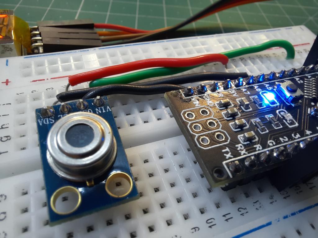
MLX90614:
The MLX90614 Temperature Sensor is capable of measuring the temperature of a particular object or surface without getting into contact with it. The sensor works measuring the amount of IR light emitted by an object towards which it is pointed at, it uses the principle of Stefan-Boltzmann Law which states that all objects including living being, emit IR energy based on the temperature of the object or the being. Hence by measuring the IR energy emitted, we can calculate the temperature of the object.
Features:
· Operating Voltage: 3.6V to 5V
· Operating Current: 1.5mA
· Temperature Range: -70°C to 382.2°C
Components required:
1) Arduino Nano
2) 4-digit 7 segment display
3) MLX90614 Non-contact IR sensor
4) Connecting wires
5) Custom PCB (PCBWAY)
6) 9v Battery
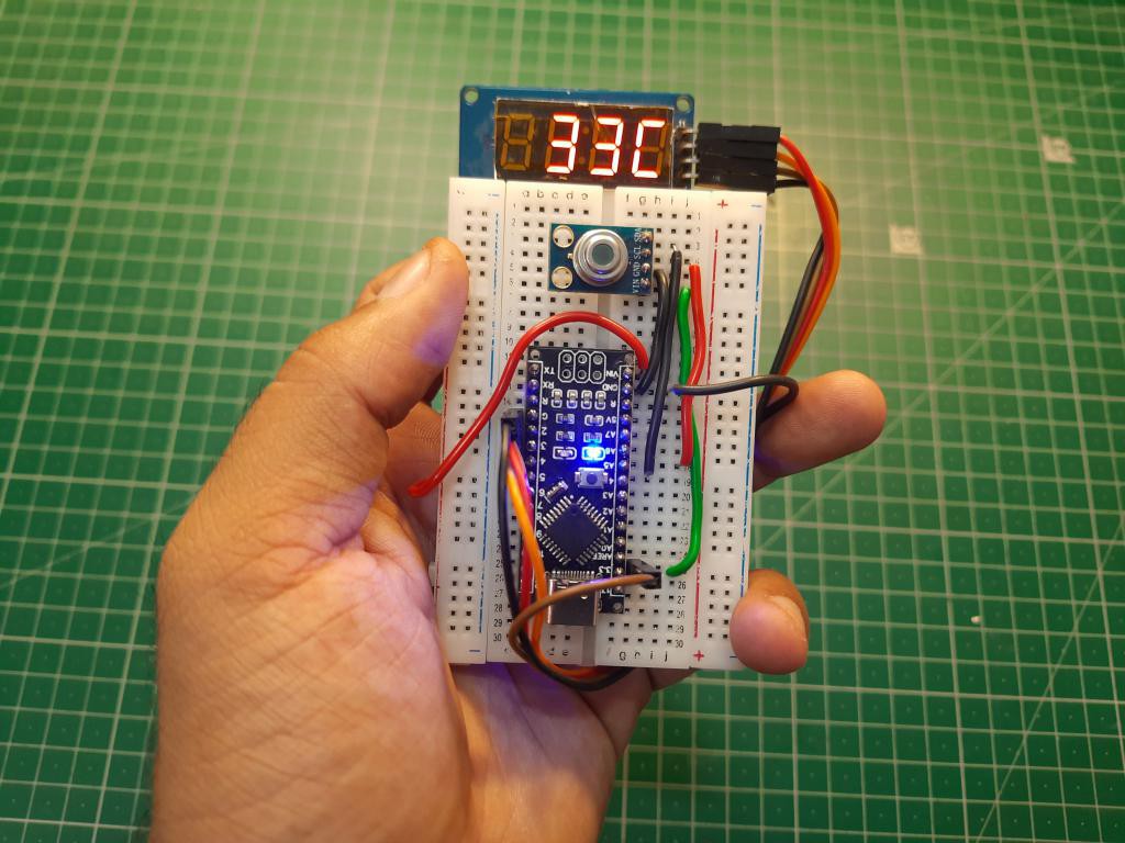
Circuit diagram:
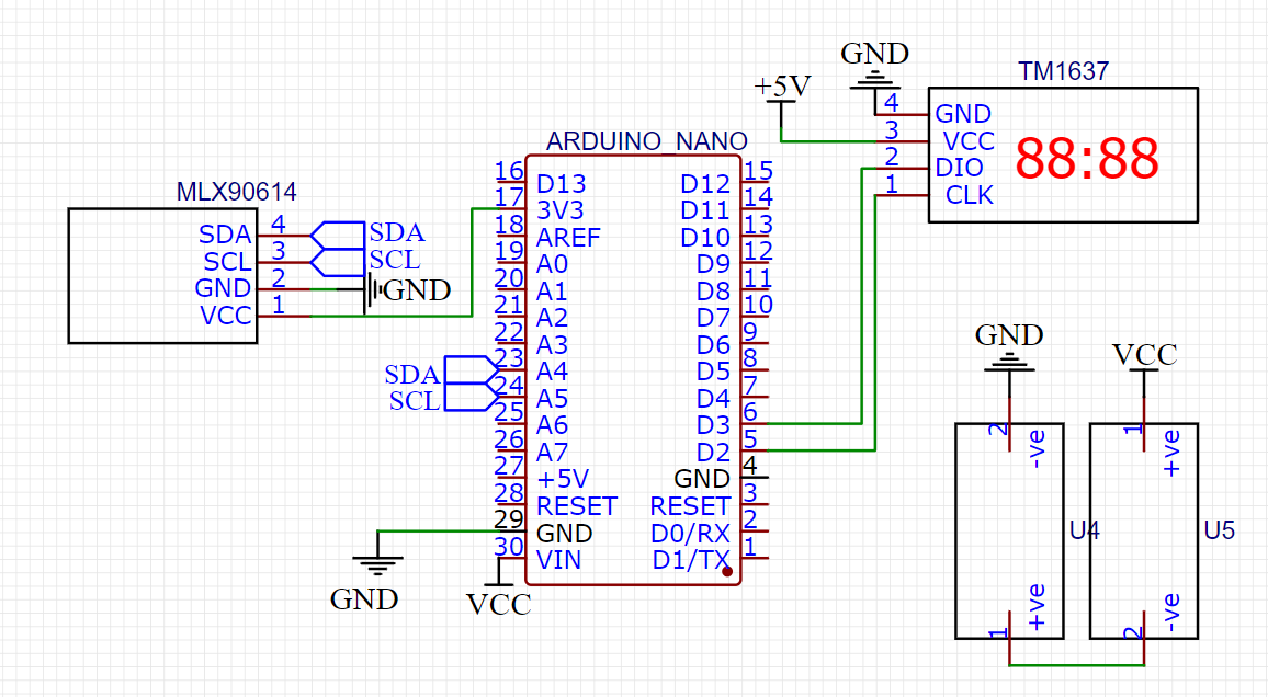
Both sensor and LCD work on 2 wire interface, Sensor use I2C communication which is connected to A4 and A5 pin of the Arduino. For the LCD clock and data, digital pins D2 and D3 are defined respectively. 9V battery is enough to power up whole the setup. Both LCD and temperature sensor works on 3.3volt.
PCB shield:
I designed this shield according to the connection diagram. Just plug the Arduino, display and sensor at their place and we are ready to go after powering the system.
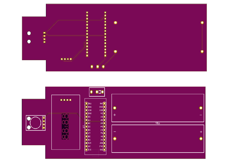
18650 battery holders can be directly mounted on the pcb.
PCBWAY UPDATE:
As you might know, I always use PCBWAY Prototypes for my projects, And now it become more easier to place an order directly for PCB manufacturing. Now Gerber files can be uploaded directly from KICAD to PCBWAY just in one click to get more info about the plugin and to install this read this article.

When you click PCBWay Plug-in button on Kicad, we will export these files in your project:
1.Gerber files in correct format for production
2.IPC-Netlist file
3.Bom-file that includes all information of components
4.Pick and Place-file used in assembly
You can click "Save to Cart" to place an order immediately after uploading the files( usually only takes a few seconds), our engineers will double check the files before the production.
Code:
#include <Wire.h>
#include <Adafruit_MLX90614.h>
#include <TM1637Display.h>
#define CLK 2
#define DIO 3
Adafruit_MLX90614 mlx = Adafruit_MLX90614();
TM1637Display display = TM1637Display(CLK, DIO);
const uint8_t celcius[] =
{
  SEG_A | SEG_E | SEG_F | SEG_D
};
#define f mlx.readObjectTempF()
#define c mlx.readObjectTempC()

void setup() {
  Serial.begin(9600);
  mlx.begin();
  display.clear();
  delay(1000);
}

void loop() {
 display.setBrightness(...
Read more »
 TheotherMike
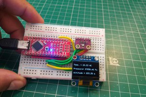
 Hulk
Hulk