 EK
EKThere are two thrusters on the device, one for suction and the other for a water jet. The water jet is used to dislodge the urchins, and the suction is used to non-destructively bring the urchins through a tube and into a bag.
Before continuing on with the assembly, it would be good to test the thrusters to validate they are working as expected. Both of the thrusters have custom pieces that attach to their mounting points and around the shell.
Electronics
The first step was to prepare the electronics:

An ESP32 was selected for rapid prototyping. There are two Electronic Speed Controllers (ESCs). Suction gets 30 A, and water jet gets 20 A.
The thruster cables will be connected to the screw terminals. The screw terminals were chosen to make it easier to disconnect when the watertight penetrators are installed onto the hull end caps.
A protoboard was used for this initial revision. Future versions will use a custom circuit board.

The power will be supplied by a 4S Li-Po battery. The ESP32 will be connected via USB to access the command line interface during testing.
Suction Thruster
The suction thruster sub-assembly consists of 6 pieces that are fastened together.

The flow redirection flange contacts the back plate of the chassis. The rectangles move the outflow of water to the sides in order to not cause distractions to the diver.
Based on the specifications, at 2000 rpm the motor will produce 2.0 kg of thrust and 75 W of power. Going up to 3000 rpm, the motor will produce 4.0 kg of thrust and 200 W of power. There is a difference in orientation of the thruster, with forward being greater than backward.
Here is a look at the thruster with the collar that uses heat-set inserts:

Water Jet Thruster
The water jet thruster was designed to have interchangeable face plates for more or less outlets to be added. The strength from the outlets must be enough to dislodge a purple sea urchin.

Rubber tubing will be attached onto each of the barbs to direct the jets closer to the entrance of the suction tube.
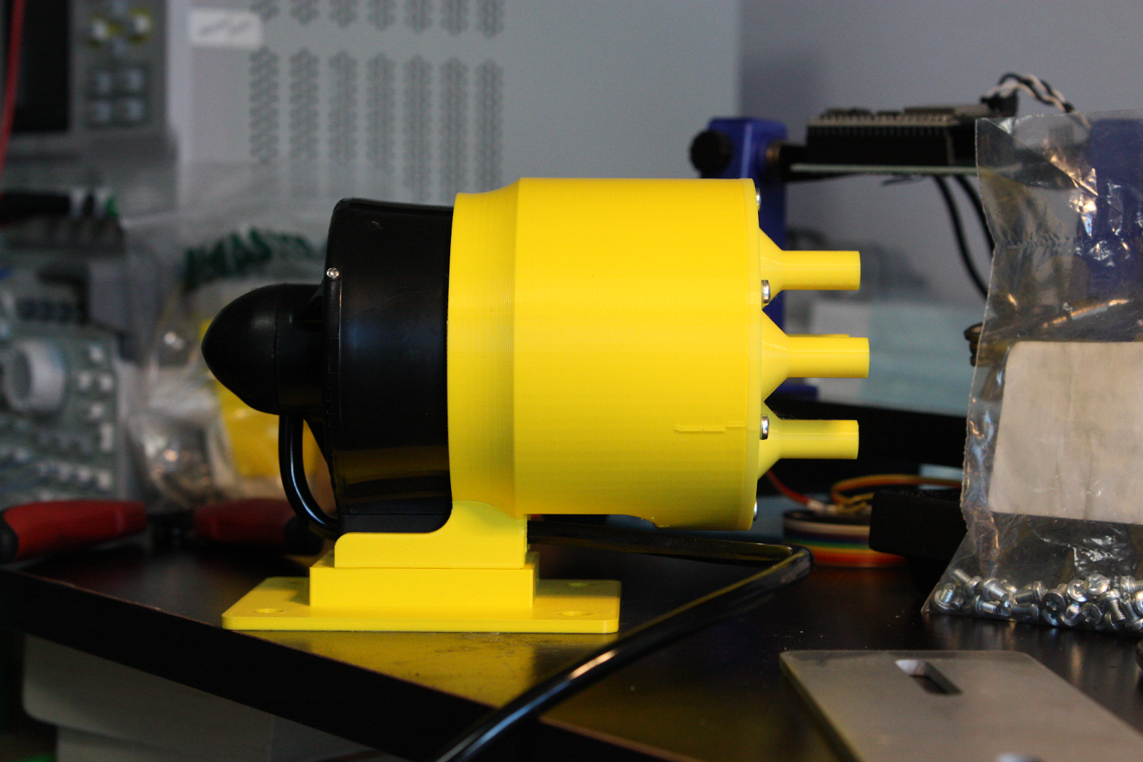
Side view of the water jet thruster sub-assembly.
Based on the specifications, this thruster can withstand up to 300 m in depth. The max power is 150 W, and the max current is 10 A. The max thrust at 16 V is 1.4 kg at 170 W, and the min thrust is -1.2 at 160 W (operating in reverse).
Upcoming Testing
A rotary potentiometer will be used to adjust the speed of the thruster, by modifying the pulse width of the PWM sent to the pin the ESC is connected to.
The firmware (https://github.com/RobotGrrl/OtterForceOne/tree/main/Firmware/OFO_ThrusterTest) has the following modes that can be input as one character:
h: Help

1: knob off

2: knob: suction fwd

3: knob: suction rev

4: knob: water jet fwd

5: knob: water jet rev

p: print knob
The test must be conducted in water as the thrusters have bearings that are lubricated by water. Running them in the open air risks damaging them.
The goal for the test is to confirm the following:
- Suction thruster operational in fwd / rev
- Water jet thruster operational in fwd / rev
- The pulse width microseconds time for minimum and maximum
The test will be conducted tomorrow. It’s going to be exciting to see the first bits of this robot come alive!
If the results meet the criteria, the next immediate step would be to start potting the thruster connectors into the watertight enclosure penetrators with marine epoxy, as this may take 24 hours to cure.

Discussions
Become a Hackaday.io Member
Create an account to leave a comment. Already have an account? Log In.