 Lithium ION
You might know component tester and its different versions made by many hobbyists. Today I have made a minimal version of this component tester, using some SMD components along with Through hole. I used Arduino Nano microcontroller as the brain of project. And after using a suitable resistor divider network you can get very accurate value of most of the components.
I want to keep it simple, so I choose 16x2 LCD screen. It is able to display all the graphics through symbols, numbers and alphabets. I am here for only sharing the experience in building nothing about the code. Code for this project can be downloaded from here. If you want to know more about the tester working and principle then refer to this 100-page manual. Which has all info about modes, screen types, Microcontrollers and software.
I made these PCB using PCBWAY prototyping service, starting from $5 for 5 PCB. I always use PCBway prototyping service for my projects to give them a better look and to reduce overall efforts. Sign-up to PCBWAY using this link to get free new user coupons.
Why minimal version:
First, to reduce the overall cost of the system. And secondly many of the Ardu-tester Arduino code give error. But through this minimal system you can test different codes and then implement one in your next project. I am making this for test purpose that’s why I don’t use any battery. Real time on bench testing gives the real behavior of the project.
Components required:
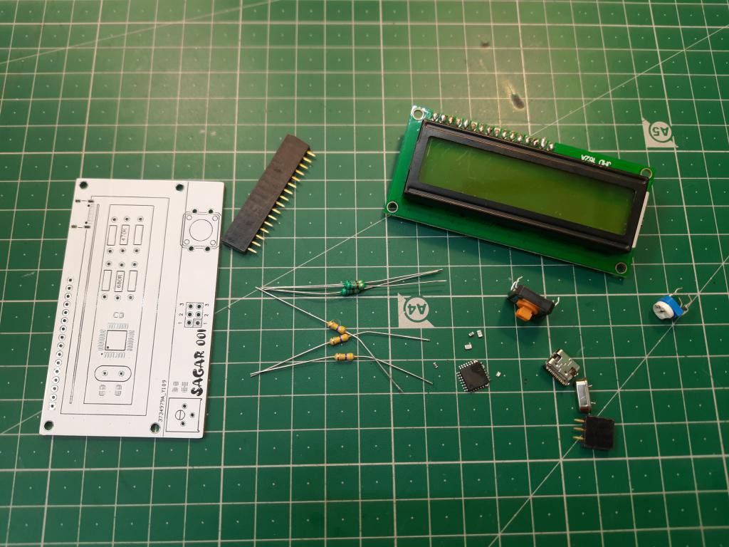
1) Arduino Nano
2) 16x2 LCD
3) 100nf capacitors
4) 1k resistor
5) 16Mhz crystal oscillator
6) 22pf capacitors
7) Type C charging jack
Circuit diagram:
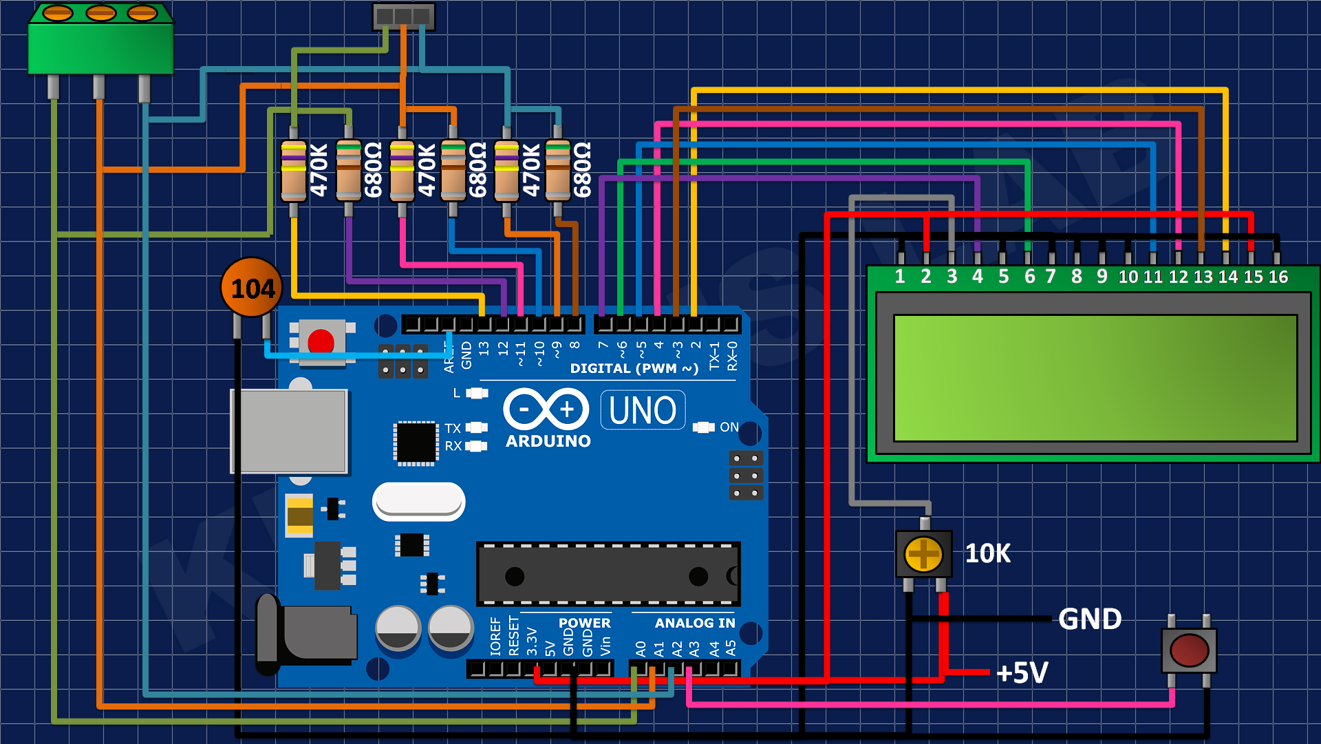
This version is limited to directly use with USB; this version doesn’t offer any protection against voltage. So, try to use a power bank or fixed value power module. A tactile button is connected to A3 pin of the Arduino which is used to reset the system and test.
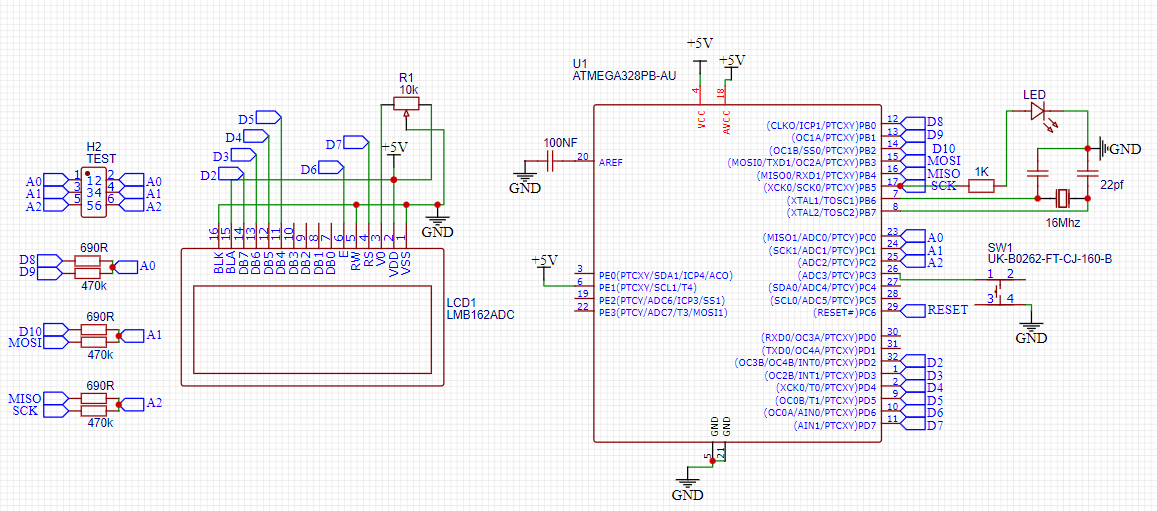
Arduino SMD microcontroller with 16Mhz crystal and 22pf capacitor for impedance matching. 470K and 680 Ohms resistor divider network is given to the ADC of Arduino. These values can be calibrated inside the code also. I always to prefer to get a microcontroller chip directly from the top of Arduino Nano after burning sketch into it.
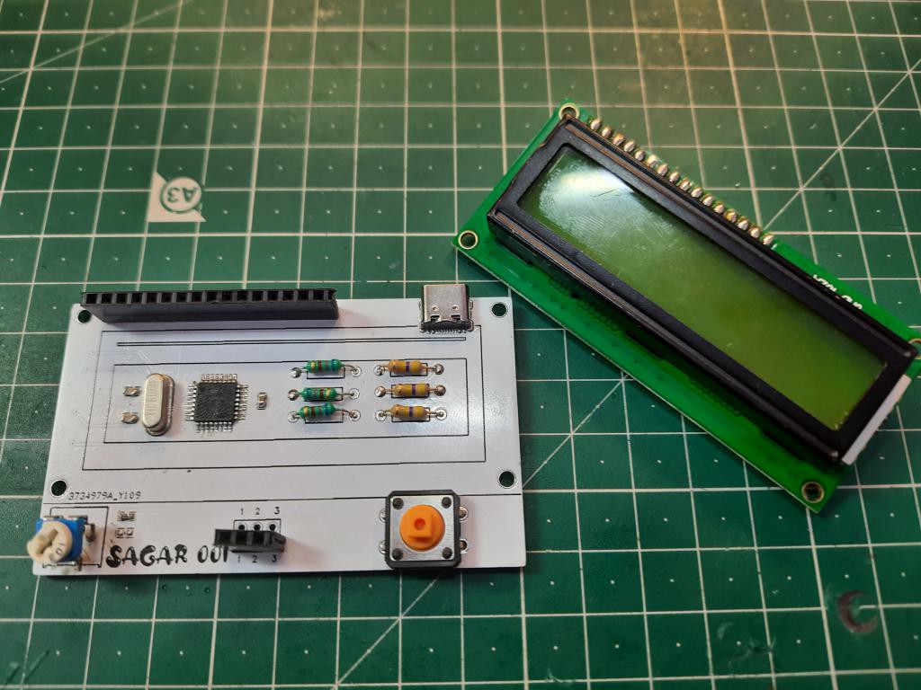
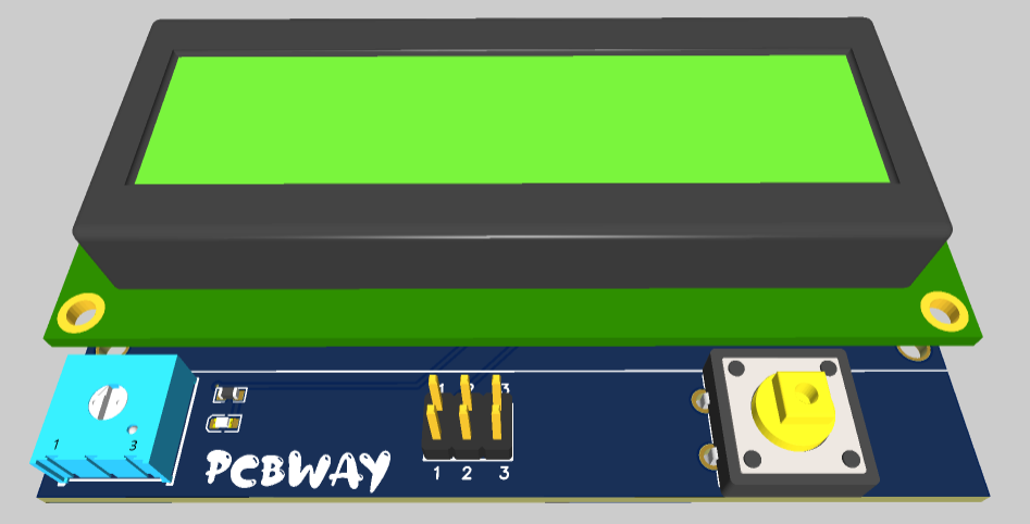
PCB designs:
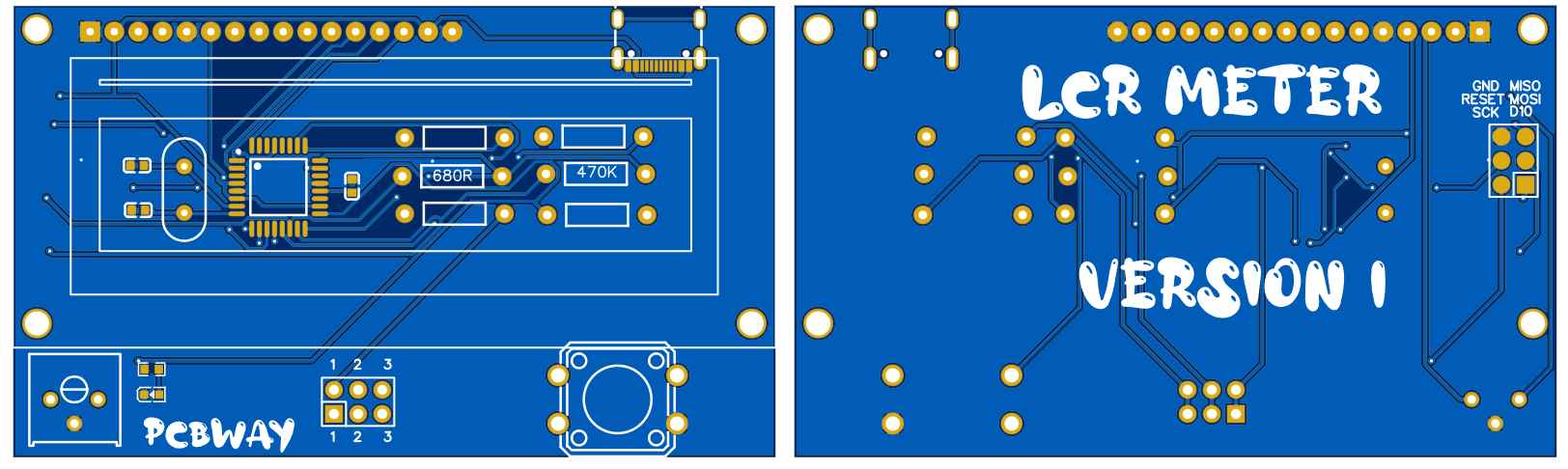
I made this minimal design using the above given modified schematics. You can download all the files and code from here. Programming headers are added on the back layer to change/ update the firmware.
I am using FR4 material, Hasl finish, white solder mask and 1.6mm thickness. A very thanks to PCBWAY for sponsoring this project. PCBway is one of leading PCB manufacturing company in China. Deals in PCB manufacturing, SMT assembly, PCBA, stencil, 3D- printing and CNC. Try out the more services from here now, and get free PCB coupons on first Sign-up using this link. Get your 5 pcs of PCB boards in just $5.
Code:
Full code can be downloaded from here, try to install the latest libraries for the LCD. You can comment here, if found any problem in uploading the code. The code calls more than 10 files, so don’t get confuse with that only keep focus on Ardu-tester_1_13 and upload it using simple steps.
Working:
This component tester can test all of the passive components and most of Active components. Like- Resistor, capacitor, inductor, Transistor, UJT, Mosfet, IGBT, Diode and LEDs. Here I made some tests using my version:
This version not only tells the value of component but also give a small usable datasheet like for a transistor its pins, configuration and gain can be obtained.
Testing Mosfet:
Testing Capacitor:
Testing Inductor:
You may refer to a YouTube channel named as eevblog who actually explained the working of resistor divider network and how wisely this meter is designed. Using a very less external circuit this meter covers almost every electronic component. The software is very optimized and thanks to maker to give us such an extraordinary device.
Ordering PCB from PCBWAY:
PCBway has introduced a new plugin for the KICAD, now you can directly add your designed Gerber into PCBWAY cart. Here are few steps you may follow to add this plugin into your KICAD software.
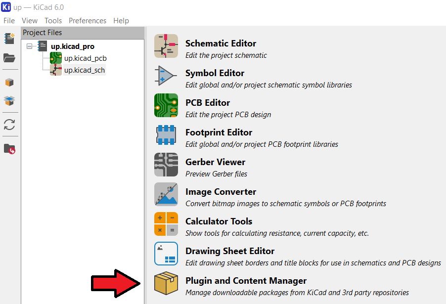
Open the KICAD designer and click on plugin and content manager.
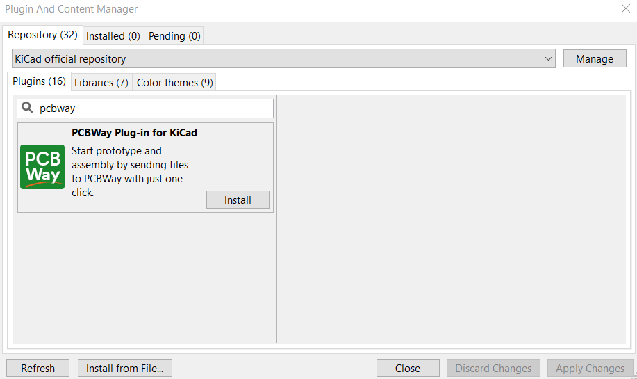
Write PCBWAY in repository then download and install the latest version.
To update the plugin in real time in editor, go to the tools menu and then to the external plugins, refresh the system, it will update the settings and then show a PCBWAY logo on the toolbar. Which redirects to PCBWAY webpage and upload the Gerbers directly.
Next version:
We will reduce the overall connection by using a 12c module with 16x2 LCD. And a small battery with proper charging and protection features. And a new version of software to fix all the existing bugs and adds new features also with hardware.