 BleakyTex
Reading signals from a Geiger tube
There are two ways to read the signal — from the anode and from the cathode of the tube:
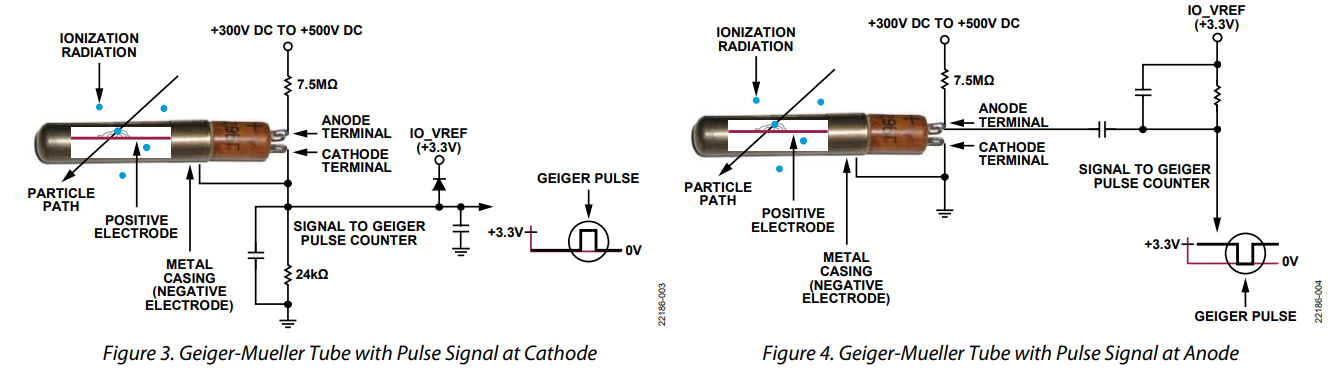
I'll be reading signals from the anode because it's more convenient to route the PCB this way and this approach provides more immunity to electrical noise. In case of anode readout, the main goal is to reduce the pulse amplitude, so it doesn't destroy the MCU. The schematic is as follows:
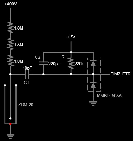
C1 and C2 act as a capacitive divider, attenuating pulse amplitude. C1 must be rated for more than 400V, I'm using a 2kV rated one. R1 is just a pull-up resistor: because the pulse is negative going, the idle voltage level should be high. I am deliberately not using MCU's internal pull-up resistor here because its value is too low, and it will shorten the pulse too much because of that. The diodes are used to clip the pulse amplitude to a safe level. Let's see how the output pulse will look like when a Geiger tube registers a radiation event:
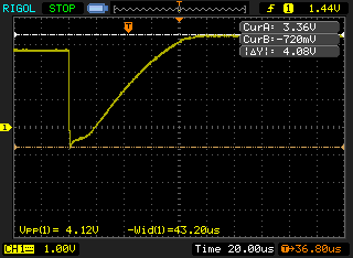
The output pulse swings from supply to ground with some overshoot due to voltage drop in diodes. High amplitude of the pulse allows us to use a digital input to register it.
Making loud clicks
I would like to be able to hear when a radiation event is registered, and I want it loud. There are two types of sound transducers — magnetic and piezoelectric. Magnetic ones require high current, so they're out of the question, also they're not that loud compared to piezoelectric. The problem with piezoelectric transducers is that they require high voltage to produce a loud sound, so we need the means to generate high voltage pulses. Here's what I came up with:
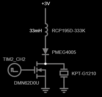
This circuit works similar to a boost converter. When the transistor is open, the inductor starts building up current and the remaining charge in the transducer is removed to increase voltage swing across it (electrically they behave like capacitors, so they can hold some charge). When the transistor closes, the energy that the inductor had at that time, is transferred into transducer's capacitance and it stays there until the next cycle. I've created a simulation if you want to take a closer look at the circuit's operation.
I'm using a KPT-G1210 transducer, it's rated for 30V, so let's generate voltage somewhere in this vicinity. As I said before, the energy EL held by an inductor is transferred into transducer's capacitance:
where:
- Et — energy, held by transducer's capacitance
- L — inductance value
- IL(pk) — peak inductor current
- Ct — transducer's capacitance
- Vt — voltage that the transducer will build up
From the formula above we get:
where
In this case, Ra is the sum of inductor's series resistance and MOSFET's drain-source resistance. We can control two parameters in this circuit — the inductor value and its charging time tON. I've selected a 33mH inductor to reduce its peak current; LR44 battery has high ESR, so if we pull too much current from it, we may get brownouts at low battery levels. This leaves us only with the tON to figure.
We'll be using a TIM2 timer in the MCU to generate pulses. It has a one-shot mode and an external trigger, so we'll set it to produce a single pulse of fixed length when its trigger input TIM2_ETR detects a falling edge from the Geiger tube. I've added this code to the TIM_Init() function:
  /* TIM2 SETUP (ONE-PULSE MODE, EXT. TRIGGER) */
  PB_DDR_bit.DDR2 = 1;         // Set PB2 as output (TIM2_CH2)
  PB_CR1_bit.C12 = 1;          // Set PB2 as push-pull
  CLK_PCKENR1_bit.PCKEN10 = 1; // Enable TIM2 clock
  TIM2_ARRH = 0;
  TIM2_ARRL = 6;           // Pulse length = 30.52uS * TIM2_ARRL
  TIM2_CCR2H = 0;
  TIM2_CCR2L = 1;
  TIM2_CCMR2_bit.OC2M = 7; // PWM mode 2
  TIM2_CR1_bit.OPM  = 1;   // One-pulse mode

  TIM2_SMCR_bit.TS  = 7;   // Trigger source - external
  TIM2_ETR_bit.ETP  = 1;   // Trigger on falling edge
  TIM2_SMCR_bit.SMS = 6;   // Start the timer on ext. trigger
  TIM2_CR2_bit.MMS = 2;    // Update event -> trigger output

  TIM2_CCER1_bit.CC2E = 1; // Enable channel 2 output
  TIM2_BKR_bit.MOE = 1;    // Enable main output
The length of the pulse that this timer generates, can only be a multiple of its clock period: 1 / 32.768 kHz = 30.52 µS. Let's see what voltage we'll get with a pulse that's 6 clock periods long — 183.1 µS.
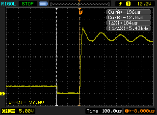
Close enough, 27V, and the MCU generates a pulse of correct length as well. The oscillation after the pulse is because the transducer continues to vibrate after making a clicking sound, generating voltage. Now let's hear how the clicks sound like.
Hackaday didn't let me embed a video from Imgur, so here's a link to it. The video shows a completed device but the clicking will work with the code and circuits provided so far.
This is actually quite loud for such a small transducer; I can easily hear the clicks from another room.
Counting radiation events
Just having a clicking dosimeter isn't enough, there should be quantitative measurements. To make these measurements, we should somehow count the radiation events. And since we have another timer to spare, we'll use it for this. We will set timer TIM3 to increment its counter whenever it sees that TIM2 produced a pulse.
  /* TIM3 SETUP (TIM2's PULSE COUNTER) */
  CLK_PCKENR1_bit.PCKEN11 = 1; // Enable TIM3 clock
  TIM3_SMCR_bit.TS  = 3;       // Trigger source - TIM2
  TIM3_SMCR_bit.SMS = 7;       // Trigger increments timer's counter
  TIM3_CR1_bit.CEN = 1;        // Start the timer
This works independently from the CPU as well, so we can read the quantity of registered radiation events whenever we want.
Discussions
Become a Hackaday.io Member
Create an account to leave a comment. Already have an account? Log In.