 BleakyTex
Setting the update interval
To save power, I've decided to update the display once in 5 seconds. Dose rate is a statistical value, so there's not much point to update it faster. Between updates we can stop the CPU, since the boost converter and the radiation event counter work independently of it. We have one last timer to spare, and we're going to use it to generate CPU wakeup interrupts every 5 seconds. After wakeup, we'll update the dose rate and total dose values and put the CPU back to sleep until the next interrupt. First, we should set up the timer:
  /* TIM4 SETUP (5-SEC INTERRUPTS) */
  CLK_PCKENR1_bit.PCKEN12 = 1; // Enable TIM4 clock
  TIM4_PSCR_bit.PSC = 0xE;     // Div by 16384 -> 0.5 sec resolution
  TIM4_ARR = 9;                // 5-second period (sec =  + 1) / 2)
  TIM4_EGR_bit.UG = 1;         // Update timer registers to apply prescaler value
  TIM4_CR1_bit.CEN = 1;        // Start the timer

  TIM4_IER_bit.UIE = 1;        // Enable TIM4_UIF interrupt (timer overflow)
  WFE_CR3_bit.TIM4_EV  = 1;    // TIM4 interrupts can wake the CPU from Wait mode
And then we just call the update function when the CPU is woken up by interrupt from TIM4 and then put it back into Wait mode after the function is executed:
int main(void)
{
...
  FLASH_CR1_bit.WAITM = 1;   // Disable Flash memory during Wait mode

  while(1)
  {
    if (TIM4_SR1_bit.UIF == 1) {
      TIM4_SR1_bit.UIF = 0;  // Reset interrupt flag
      app_readGeiger();
    }

    asm("WFE");  // Enter Wait mode
  }
}
Notice that this happens in the main loop, there is no interrupt handler. Since there's nothing time-critical happening here, we don't need them, we'll just waste precious CPU cycles to enter and exit an interrupt.
Reading the event counter and applying dead-time correction
The challenge with reading the value from the timer is that the event may occur during reading process, causing rollover or missed readings. Also, we should apply dead-time correction to the value we've read because at high counting rates, a Geiger tube may not have enough time to recover to register pulses occurring at quick succession, which leads to reduced measured activity. The equation for the dead-time correction is:
where N — true counting rate (in events per second), n — measured counting rate, Td — dead time of the tube. This equation is meant for 1-sec measurement intervals, and we're measuring with 5-sec intervals. This will reduce the dead-time effect by 5. The dead time of SBM-20 tube is 190µS, so the effective dead time will be 190/5 = 38µS:
This equation involves floating-point numbers and will be too challenging to calculate for an 8-bit microcontroller, running at 32.768 kHz. We can simplify it with a polynomial approximation:
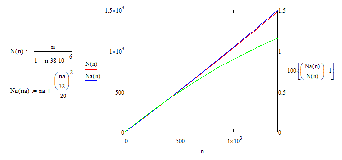
The deviation increases with n, and at 1400 CPS the approximation gives a value, that's 1.15% higher than the original equation gives. Not too much accuracy to lose, given a massive performance gain that we get from this approximation, isn't it? Let's write the code. Since we need to read and clear the timer as fast as possible, I'll use assembly to do this. And while I'm at it, I'll do the dead time correction in assembly as well. You can check the STM8 programming reference (PM0044) if something isn't clear.
uint16_t cp5s;                 // Registered events during 5-sec interval

void app_readGeiger(void)
{
  // Read and clear TIM3 counter
  // TIM3_CNTRH must be read first to prevent rollover
  asm("LD   A, TIM3_CNTRH");
  asm("CLR  TIM3_CNTRH");
  asm("PUSH TIM3_CNTRL");
  asm("CLR  TIM3_CNTRL");
  asm("PUSH A");
  asm("LDW  X, (0x01, SP)"); // now both stack and register X hold cp5s value

  // Apply dead time correction: cp5s = cp5s + ((cp5s/32)^2 / 20)
  // This equation is a polynomial approximation of N = n / (1 - n*38e-6)
  asm("LD   A, #32");
  asm("DIV  X, A");   // cp5s/32
  asm("LD   A, XL");
  asm("MUL  X, A");   // ^2
  asm("LD   A, #20");
  asm("DIV  X, A");   // /20
  asm("ADDW X, (0x01, SP)"); // + cp5s
  asm("POPW Y");
  asm("LDW  cp5s, X"); // cp5s =
}
Only 15 instructions, not too bad. The rollover is prevented by using the fact that the MCU locks the timer counter value if we first read the TIM3_CNTRH register and unlocks it after TIM3_CNTRL is read. Thus, our timer ignores radiation events for only 4 instructions (CPU cycles) every 5 seconds.
Calculating radiation dose rate
Dose rate is a statistical value, and a 5-sec interval is not enough to get a reasonably accurate measurement. A reasonable trade-off between accuracy and response time is a 1-min measurement. But how to update the display every 5 seconds if our measurement interval is 1 minute? One way to calculate counts-per-minute (CPM) is from a rolling sum of 12 consecutive 5-sec measurements. Every 5 seconds a new measurement is added to the sum and 12th last is subtracted from it. Algorithmically it looks like this:
cpm -= event_buf[event_idx];
cpm += cp5s;
event_buf[event_idx] = cp5s;
++event_idx;
if (event_idx > 11) event_idx = 0;
This way we can update the dose rate value every 5 seconds. After getting the CPM value, we can calculate a dose rate value (µSv/hr) from it by multiplying CPM by a tube-specific coefficient, k = 0.0052 in case of SBM-20 tube:
Floating point numbers again, let's see how we can transform this to only use integers. The maximum dose rate resolution that makes physical sense is 0.01 µSv/hr, so we can keep the dose rate in a form of hundredth parts of µSv/hr: 0.01 = 1, 0.02 = 2 etc. Then we can multiply the coefficient k by 100:
Here dose_rate is an integer variable, and now we can use simple integer operations to find its value.
Now let's talk about precision. Radiation events occur at random, so we should apply statistical rules when evaluating dose rate. Suppose we've measured 0.1 µSv/hr. This is equivalent to n = 20 registered events during 1 minute for SBM-20 tube. Coincidentally, this is where we're starting to get Gaussian probability distribution (n ≥ 20), so we can apply the following equation to estimate measurement precision:
For such a low radiation level, I think this is acceptable. Obviously, as n increases, precision will increase.
Calculating total radiation dose
This dosimeter is designed to measure radiation dose up to 999 mSv. This is a lot of radiation events to keep in memory and the math will get ugly very fast if we don't simplify it (for the microcontroller, not for us). To find the accumulated radiation dose from total number of counted events, we can transform the equation for µSv/hr:
where N - counts per µSv. Number 60 comes from the number of minutes in 1 hour. The formula is for µSv per hour, but the coefficient is for counts per minute. And yes, we need this much precision to get an accurate result on the whole span of possible dose values, so obviously, we need to come up with a fast algorithm to update the dose. Here's what I came up with.
We can have multiple display modes and update the displayed number every time the event counter reaches certain value. Then we subtract this value from the counter. The maximum counting rate for SBM-20 is 1400 CPS, which will give us maximum cp5s = 1400 ⋅ 5 = 7000 events. This is equal to 0.6 µSv dose, so it's more convenient to handle first two display modes separately, because the dose value in them can increase by more than 1 between display updates.
| uint8_t mode | uint16_t dd | int32_t dose | int32_t LUT[] | |
| Display mode | Display format | Resolution | Events per 1 digit | Algorithm |
| 0 | 9.99 µSv | 0.01 µSv | 115 | dd += 10*(dose / 1153);
dose %= 1153;
dd += dose / 115;
dose %= 115;
if (dd > 999) {
++mode;
dose += (dd % 1000) * 115;
}
|
| 1 | 99.9 µSv | 0.1 µSv | 1153 | dd += 10*(dose / 1153);
dose %= 1153;
if (dd > 999) {
++mode;
dose += (dd % 1000) * 1153;
}
|
| 2 | 999 µSv | 1 µSv | 11538 | if (dose >= LUT[mode]) {
++dd;
dose -= LUT[mode];
if (dd > 999) ++mode;
}
|
| 3 | 9.99 mSv | 0.01 mSv | 115384 | same as 2 |
| 4 | 99.9 mSv | 0.1 mSv | 1153846 | same as 2 |
| 5 | 999 mSv | 1 mSv | 11538461 | same as 2 |
I've provided very simplified code; the actual code is very ugly because it's heavily optimized for speed, I don't see the point in posting it here. The code executes in 6.2ms on average, which is equal to 203 clock cycles. If implemented in assembly, it can be optimized to only 122 cycles. And now think how long it would take to divide a 64-bit integer (total counted events) by 11538.4615. I won't be surprised if over a 1000 cycles.
Saving data
I want the dosimeter to keep the radiation dose and dose measurement time when it's switched off. First of all, we need means to detect power loss. Since I couldn't get a proper voltage monitor, I came up with this:
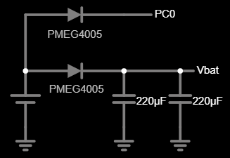
When power is lost, the voltage at MCU's pin PC0 goes to 0, triggering the shutdown sequence. The power for shutdown is provided by the capacitors. The upper diode is only for reverse polarity protection, bottom diode also prevents current from flowing from the capacitors to PC0.
Now let's save the data to EEPROM. Its access granularity is 4 bytes, so it's rational to have a data structure with a size, multiple to 4 bytes. We need to save the total accumulated dose and total measurement time: seconds, minutes, hours and days (up to 999). I've managed to cram the data into an 8-byte structure by removing the redundant bits in variables that we need to save:
struct {
  uint16_t ddisp:10;  // displayed digits of dose, 0..999
  uint16_t min:6;     // dose measurement minutes, 0..59
  uint16_t mode:3;    // dose display mode, 0..6
  uint16_t hrs:5;     // dose measurement hours, 0..23
  uint16_t dose_h:8;
  uint16_t dose_l:16; // radiation events counter, 0..11538461
  uint16_t days:10;   // dose measurement days, 0..999
  uint16_t sec:6;     // dose measurement seconds, 0..59
}state;
Notice that the bit order is such that the structure can be split into 4 bytes during write operation. During shutdown, the data is packed into this structure and written to EEPROM, and then unpacked during startup and the value of respective variables is restored.
Discussions
Become a Hackaday.io Member
Create an account to leave a comment. Already have an account? Log In.