 danjovic
Wheel of The Year
On 16 segment Display
The wheel of the year is divided in 8 intervals, and the corresponding segment is lit whenever the current day is inside the interval.
In the picture below, the segment will be lit from February 1st until March 20th
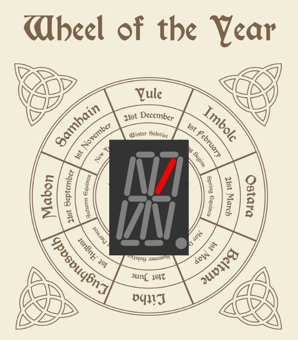
And while the weeks are passing the outer segments will start to lit sequentially, up the the point that the external wheel is complete. When the next date is reached all external segments will be turned off and the next internal segment will lit.
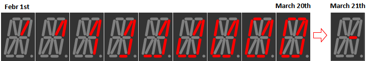
The intervals between festivals are not equally spaced, then every outer segment represents a different amount of days between the festivals.
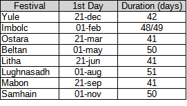
The calculation of which segments to lit is performed by a table search where the index is the current day of the year, starting at February 1st . This table has the dimension of 8 x 9 because there are 8 festivals and 9 different states for the 8 external leds, from all lit to all unlit. Every entry is therefore a threshold day.
The search start at the last element and stops at the position where the present day is less than the element in table. The position at which the search ended is used as an entry to another 8x9 table of 16 bits that represents which segments shall be lit.
const PROGMEM uint16_t dayThreshold[72] = {
 //Segment:      all   none  1seg  2seg  3seg  4seg  5seg  6seg  7seg      (next)
 /* Imbolc  */      0,    1,    6,   12,   18,   24,   30,   36,   42,  /*    48  */
 /* Ostara  */     48,   49,   53,   58,   63,   68,   73,   78,   83,  /*    89  */
 /* Beltane */     89,   90,   95,  101,  108,  114,  120,  127,  133,  /*   140  */
 /* Litha   */    140,  141,  145,  150,  155,  160,  165,  170,  175,  /*   181  */
 /* Lammas  */    181,  182,  187,  193,  200,  206,  212,  219,  225,  /*   232  */
 /* Mabon   */    232,  233,  237,  242,  247,  252,  257,  262,  267,  /*   273  */
 /* Samhain */    273,  274,  279,  285,  291,  298,  304,  310,  316,  /*   323  */
 /* Yule    */    323,  324,  328,  333,  338,  343,  348,  353,  358   /*   364  */
};
//

const PROGMEM uint16_t seasonPattern16segment[72] = {
    _Imbolc_, _Imb_s0_, _Imb_s1_, _Imb_s2_, _Imb_s3_, _Imb_s4_, _Imb_s5_, _Imb_s6_, _Imb_s7_,
    _Ostara_, _Ost_s0_, _Ost_s1_, _Ost_s2_, _Ost_s3_, _Ost_s4_, _Ost_s5_, _Ost_s6_, _Ost_s7_,
    _Beltane, _Bel_s0_, _Bel_s1_, _Bel_s2_, _Bel_s3_, _Bel_s4_, _Bel_s5_, _Bel_s6_, _Bel_s7_,
    _Litha__, _Lit_s0_, _Lit_s1_, _Lit_s2_, _Lit_s3_, _Lit_s4_, _Lit_s5_, _Lit_s6_, _Lit_s7_,
    _Lammas_, _Lam_s0_, _Lam_s1_, _Lam_s2_, _Lam_s3_, _Lam_s4_, _Lam_s5_, _Lam_s6_, _Lam_s7_,
    _Mabon__, _Mab_s0_, _Mab_s1_, _Mab_s2_, _Mab_s3_, _Mab_s4_, _Mab_s5_, _Mab_s6_, _Mab_s7_,
    _Samhain, _Sam_s0_, _Sam_s1_, _Sam_s2_, _Sam_s3_, _Sam_s4_, _Sam_s5_, _Sam_s6_, _Sam_s7_,
    _Yule___, _Yul_s0_, _Yul_s1_, _Yul_s2_, _Yul_s3_, _Yul_s4_, _Yul_s5_, _Yul_s6_, _Yul_s7_
};
//

// show season on 16 segment display
void showSeason16Seg ( uint16_t dayOfYear ) {
  uint8_t th = 71;  // count down to next threshold

  while ( dayOfYear < pgm_read_word (dayThreshold + th ) ) {
    th--;
  }

  // set correspondent pattern
  displ16SegBuffer =  pgm_read_word( seasonPattern16segment + th ) ;
}
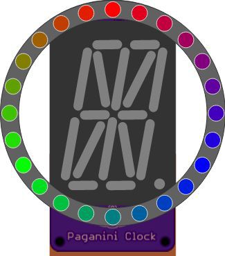
On LED Ring
A second representation of the Wheel of the Year uses the LED ring to display the season, this time using colors. Again, a table search was used having the day of the year as the search term. The index is the position of the LED to be lit and is also used to get the color coordinates from another table.
const PROGMEM uint16_t dayThreshold24intervals [24] = {
     12,  30,  48, 58 ,  73,  89, 101, 120, 140, 150, 165, 181,
    193, 212, 232, 242, 257, 273, 285, 304, 323, 333, 348, 364
};
//
const uint8_t PROGMEM seasonColors[24][3] = {
    { 0xFF, 0x00, 0x00 } , // RED
    { 0xE1, 0x00, 0x1E } , //
    { 0xC0, 0x00, 0x3F } , //
    { 0xA2, 0x00, 0x5D } , //
    { 0x81, 0x00, 0x7E } , //
    { 0x60, 0x00, 0x9F } , //
    { 0x42, 0x00, 0xBD } , //
    { 0x21, 0x00, 0xDE } , //
    { 0x00, 0x00, 0xFF } , // BLUE
    { 0x00, 0x1E, 0xE1 } , //
    { 0x00, 0x3F, 0xC0 } , //
    { 0x00, 0x60, 0x9F } , //
    { 0x00, 0x7E, 0x81 } , //
    { 0x00, 0x9F, 0x60 } , //
    { 0x00, 0xC0, 0x3F } , //
    { 0x00, 0xDE, 0x21 } , //
    { 0x00, 0xFF, 0x00 } , // GREEN
    { 0x21, 0xDE, 0x00 } , //
    { 0x3F, 0xC0, 0x00 } , //
    { 0x60, 0x9F, 0x00 } , //
    { 0x81, 0x7E, 0x00 } , //
    { 0x9F, 0x60, 0x00 } , //
    { 0xC0, 0x3F, 0x00 } , //
    { 0xE1, 0x1E, 0x00 } , //
};

// show Season using color table
void showSeasonLedRing ( uint16_t dayOfYear  ){
    uint8_t th = 23;  // count down to next threshold
  while ( dayOfYear < pgm_read_word (dayThreshold24intervals + th ) ) {
    th--;
  }
    // set LED color according to season
    clearLeds ( &ledRing) ;
    ledRing.led[ th ].red    = ( pgm_read_byte( &(seasonColors[th][0])) * ledRingBrightness ) >> 8;
    ledRing.led[ th ].green  = ( pgm_read_byte( &(seasonColors[th][1])) * ledRingBrightness ) >> 8;
    ledRing.led[ th ].blue   = ( pgm_read_byte( &(seasonColors[th][2])) * ledRingBrightness ) >> 8;
}
//
Two tables of 72 elements of 16 bit and took 288 bytes. Add more 120 bytes from the color ring representation and we have 408 bytes. It may seem too much for the Tiny85 but the simplicity payed off. Furthermore that was not the main issue related to flash memory usage.
24/12h Clock
A second use of the LED ring is to show the time. There are two modes available - 24h and 12h.
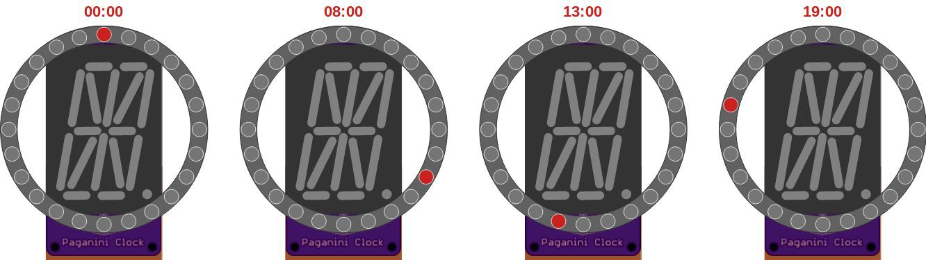
24h mode
In this mode every led is lit at a time and a full circle represents 24h. The color is always red to blend with the 16 segment display. This was the original clock
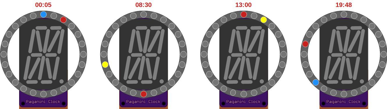
12h mode
The second mode is the 12hour where one of the leds is static and represents the hours and the other led blinks at 1Hz and represents the minutes. The indication of AM/PM is performed by the color of the Hours LED (not quite AM/PM but daylight and night time)
- From 06:00 to 17:59 hour is indicated by yellow led (because sun is yellow)
- From 18:00 to 05:59 hour is indicated by blue led (because night hues are blueish)
The minutes are always red. Not actually a minute because every led represents an interval of 2m30s.
At the intersections the "minutes" led blinks from green to yellow during daytime and from magenta to blue in night time.
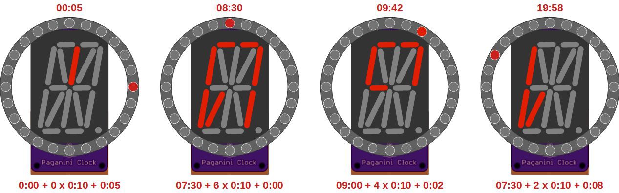
Ultradian Mode
In this mode both the 16 segment display and the NeoLED ring are use to display time.
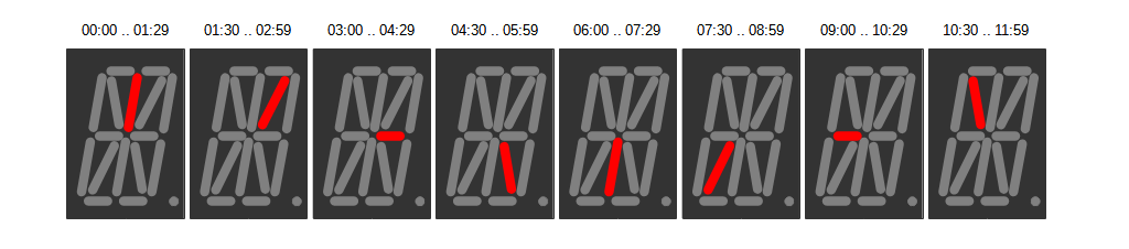
The 16 segment time indication was inherited from from a sidekick project, where the hour are represented with some resemblance with traditional clocks, using the inner segments to represent 90 minute intervals, while the periphery segments represent a 10 minute interval each, ranging from 0 (no segment lit) to 80 (all periphery segments lit.
The external ring represents intervals of 25 seconds each, so after a full circle we have 10 minutes, hence the corresponding positions of 3h, 6h, 9h on a traditional clock represent 2:30, 5:00 and 7:30 minutes respectively.
Circuit
The Paganini Clock is built upon the following components:
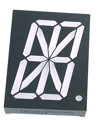
- 2" tall 16 Segment display
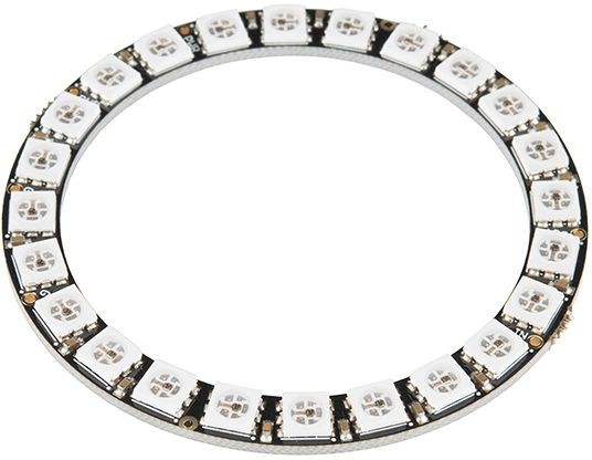
- NeoLED ring with 24 LEDs
- DigiSpark board
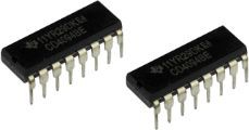
- CD4094 shift Registers (2x)
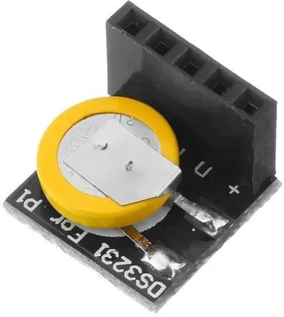
- DS3231 RTC Module
- Tactile switches (2x)
There are only 6 pins available on the Digi-Spark and they all are used, including the reset pin. It might be necessary to reprogram the fuses of the board to enable the reset pin to work as an I/O pin which can be achieved following this instructions.

The allocation of pins is depicted below:
//                        ATTiny85
//                       +--+__+--+
//    ADC0/BUTTONS  PB5 [|1      8|] Vcc
//                       |        |
//         SCK/RCK  PB3 [|2      7|] PB2  SCL (I2C)
//                       |        |
//   DOUT LED RING  PB4 [|3      6|] PB1  SHIFT DATA OUT
//                       |        |
//                  GND [|4      5|] PB0  SDA (I2C)
//                       +--------+
RTC
Pins PB0 and PB2 are used as SDA and SCL respectively for I2C RTC module, a DS3231 said to be RTC for Raspberry PI. Such module provides a couple of pullup resistors, so no need to add them externally.
16 Segment Display
PB1 and PB3 are used to shifth the 16 segment data out to the CD4094s. I have seen some projects using the outputs of these chips to feed 7 segment LED displays directly and used the same expedient here. Two chips were cascaded to drive the 16 segments.
The Display is a Common Anode, 2 inch tall 16 Segment in RED color.
NeoLED Ring
PB4 is used to shift out NeoLED data using WS2812 protocol it has 24 LEDs distributed along circle with 1.5" radius (to the center of each LED)
Tactile Switches
PB5 is used to read both tactile switches using the ADC module. Any key pressed will provide a given voltage. The value of the resistances were chosen to provide also a "both" key pressed indication (though this feature were not used in the code)
To be continued