Close
0%
0%

Sensing spider prank (Wood Edition)

In this project, you will learn multiple aspects of Arduino while building an automated sensing spider.

Similar projects worth following
205 views
Halloween is coming and spiders are perfect for creating a good scare. This project can be either 3D printed or made from wood. A great and challenging introduction to Arduino that demonstrates a practical use of multiple inputs and outputs.

Using a PIR sensor our target is automatically detected and our spider deployed rapidly for the perfect fright.

Check the video links if you get stuck on a step these are timestamped so should go directly to the place you are at.

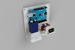
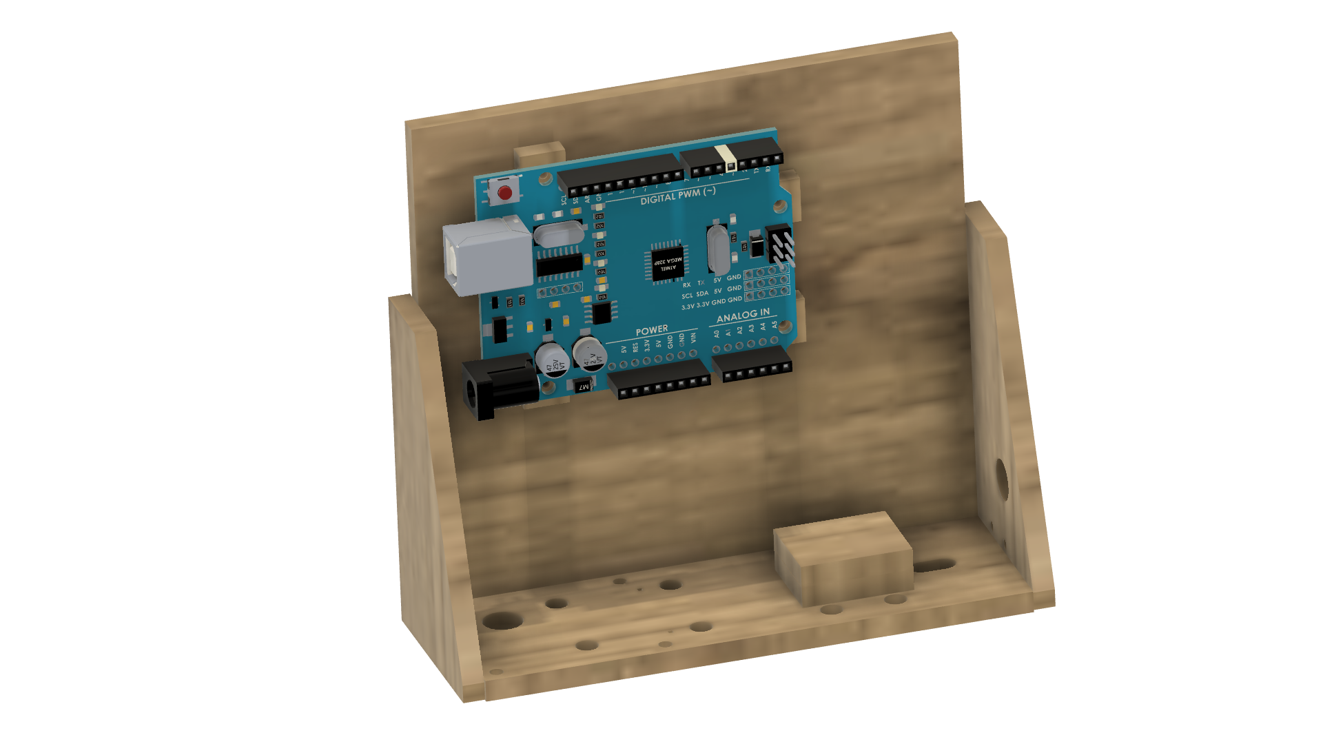
The project uses an Arduino UNO to sense our victim with a PIR sensor. Once they have been detected a small DC motor with a spool of cotton unwinds to deploy our spider. A microswitch keeps a check on our spider to make sure it doesn't get too carried away. 

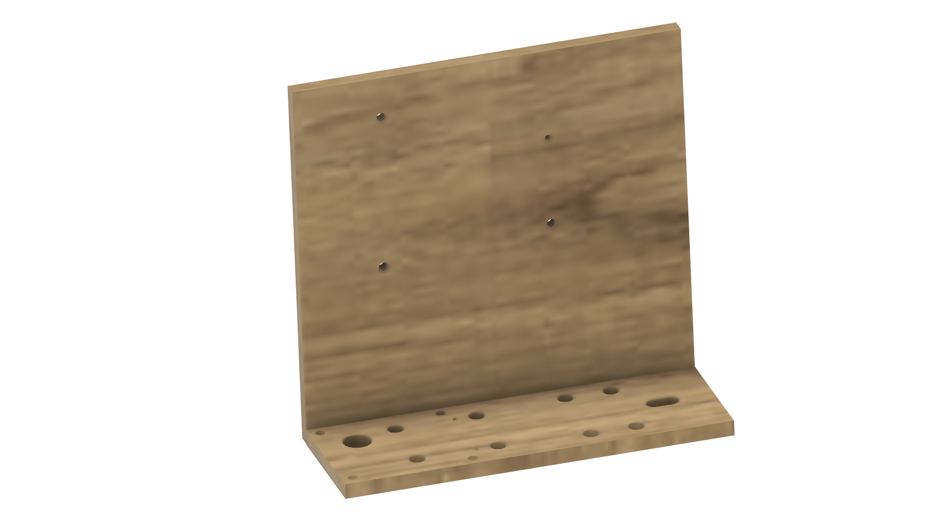
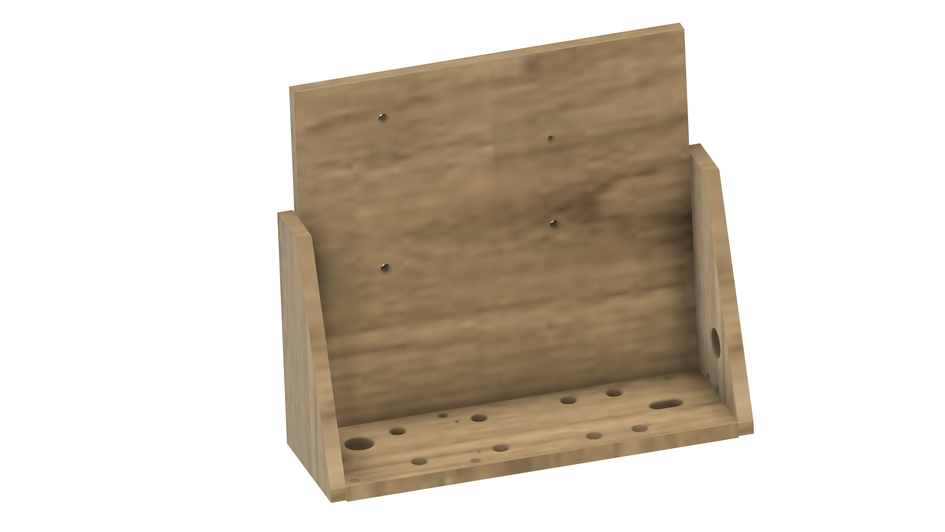
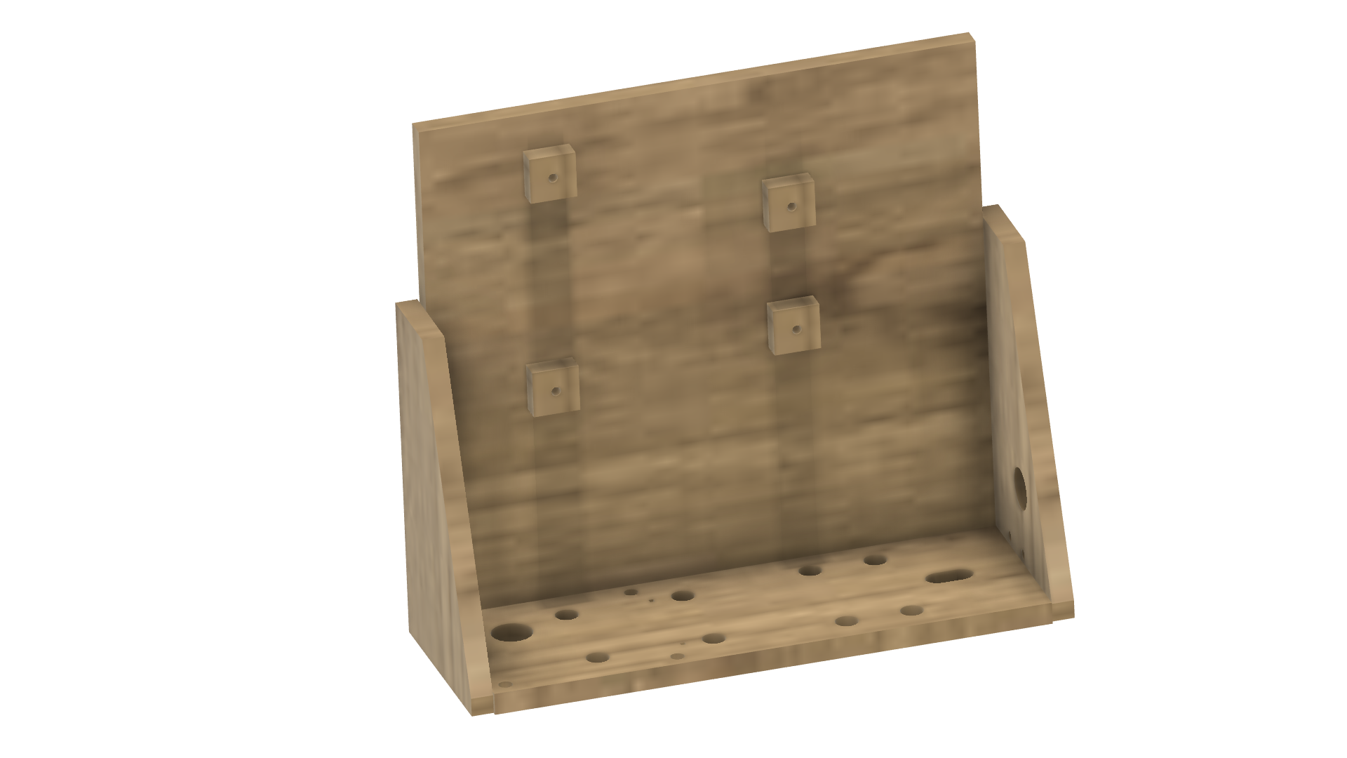
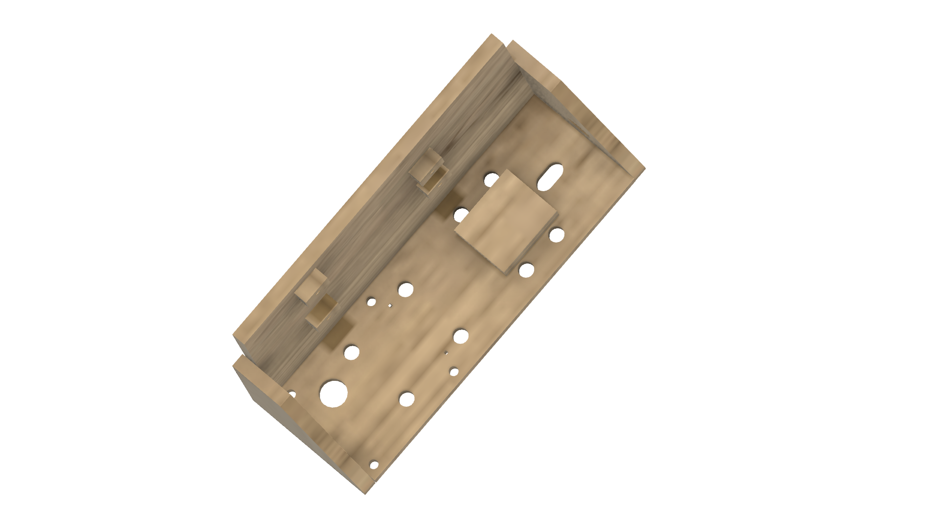
The project has STLs if you have access to a 3D printer or templates for cutting out on wood or a laser template for laser cutting. 

If you are new to Arduino this is the perfect project to build something and see a practical outcome. 

All the code is included and the parts should be readily available throughout the world.

Adobe Portable Document Format - 4.07 kB - 10/13/2022 at 00:34

Preview
Download

Adobe Portable Document Format - 5.35 kB - 10/13/2022 at 00:22

Preview
Download

Adobe Portable Document Format - 331.09 kB - 10/12/2022 at 23:55

Preview
Download

Standard Tesselated Geometry - 4.42 MB - 10/12/2022 at 23:50

Download

View all 14 components

  • 1
    Cut out wood chassis

    There are two options to get the chassis cut out. You can either print the PDF called template.pdf and glue this onto a piece of 4.75mm MDF or you can use the forcutting.pdf and get the wood laser cut. The laser-cut file is designed in such a way that it should only take a few minutes to cut your wood.  Either method will yield the same result. For more details see the video here

  • 2
    Glue chassis together

    Glue the base of the chassis together starting with the back and the base. You should only need a good PVA glue. Note that the holes further apart vertically on the back go to the left. For the base, the slotted hole goes to the right and the large hole on the left goes toward the back.  For more details see the video here.

    Add the left and right-hand side profiles. Note the profile with the holes goes on the right.

    Glue the mounts for the Arduino on the back. I used nails to line up the holes but you could probably just do this by sight. 

    Glue the two motor mount cut-outs together then glue these to the base of the chassis between the two cable tie holes.

  • 3
    Mount the Arduino UNO

    The Arduino UNO screws into the mount holes in the back of the chassis. The mounts might interfere with the components on the bottom of the Arduino. If this is an issue you can sand off some edges of the mounts to suit. 

View all 15 instructions

Enjoy this project?

Share

Discussions

Similar Projects

Does this project spark your interest?

Become a member to follow this project and never miss any updates