Similarly to the division of the power planes, I had some doubts about how to feed the mixed components and after several turns in the final design I see that they were a bit wrong. First of all, I don't have a clear criterion of what to do. I tried that the components with some digital signal were fed from the digital voltage, so as not to introduce noise to the analog one, but maybe that was a mistake, or maybe it is not important, but in any case I would like to clarify it with your help.
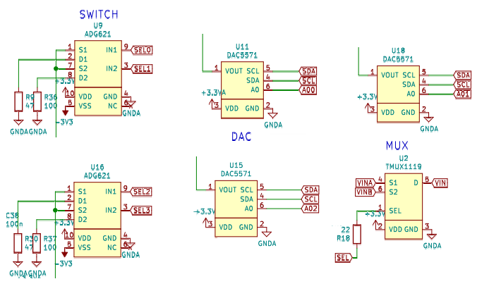
In the image above you can see several mixed components, EACH ONE WITH A DIFFERENT PATTERN! and I think this was a mistake caused by the rush and the desire to close the design and the BOM.
For example, in the case of the SWITCH, which has positive and negative power, it is clear to me that they have to go to +3v3A and -3v3A, but in one of the cases, U16, it is wrong :-(((
In the case of the DACs, U11 goes to +3v3A and GNDA, but U18 (which should be the same) and U15 go to +3v3 and GNDA, which I don't like at all. Same for the MUX U2...
The power did not cause any problem, but it is a bad design decision and above all it reflects a rush to finish.
Finally, what did cause problems and I had to fix, were the I2C tracks, many of which are inverted. I think I copied the connection order from the PICO and never checked it. Pay the price by having to cut and jumper the tracks on the actual PCB.
Discussions
Become a Hackaday.io Member
Create an account to leave a comment. Already have an account? Log In.
I'd use analog power supply for all the components that does something with analog signal.
If your SPI is not active all the time but only when changing offset or gain then you probably needn't care that much about noise introduced by this interface (you don't measure during switching range). Also it's good to slow down the transmission and add some impedance on the lines that goes from digital to analog components (resistors of ferrite beads).
The worst part is probably U2 (channel A/B switch) which may switch during measurement. I'd stay with analog power but with good filtering and decoupling (consider small, high value capacitors, e.g. 10uF 0603 very close to power pins, add ferrite beads to power supply lines). Also the signal is probably sampled when it's settled after switching U2, not during switching edges when the distortions are introduced.
Chopping the signals from both channels may distort the signal anyway, maybe try simulations before building it.
Are you sure? yes | no
Yes, all digital lines should be stable during sampling except the mux switch. In this case I will follow ur recomendations.
About simulation, there is no model for the SN74LVC2G53 on the TI website. I found the model for ADG712, similar of Benjamin choice 719 and simulate with LTSpice. The results wasent look good. Here is a switching freq of 10MHz, cause it dosnt works at 100MHz.
Are you sure? yes | no