 tobychui
Back Story
I am a electronic persons. I made a lot of projects related to electrics which require charging.
Recently I applied a booth at Taipei Maker Faire 2022 and according to my prior experience, I will need to bring a bunch of chargers with me so I can charge everything on-site and over-night for the second day event. Also recently, I have upgraded all my electronic gadgets, from my phone, laptop, Bluetooth earbuds and power bank to support USB type C. And most of my other Maker products are either powered by micro USB port or type C as well. So I was wondering, can I just bring a USB charger with enough ports to charge all my devices?
GaN Charger and Power Limitations
When I am looking for best travel charger, the first result came up was GaN chargers. They are small, light weight and powerful, come in different form factor and some of them are reasonably priced. However, most of these chargers have a fatal issues. They do not allow dynamic power allocations between ports.
Let say I have need to charge my USB PD 65W supported, 85% full laptop with my phone using a single 65W charger with configuration of 1 type C + 1 type A. The laptop might only draw around 40W (as the battery are nearly full) and my phone only draw 10W using a USB A cable. The PD charger controller will just cut the power to the USB A port because it "thinks" the laptop will use all of the 65W power. However in real life, it might be only drawing a portion of it and allow plenty of power to be delivered to the phone.
I do see some of my friend daisy chain charging their phone and wireless earbuds using their laptop as a power hub. But this way it is slow and might even overheat some ultra-book power circuitry, especially when the laptop itself is also charging. That is why I need a better solution.
Non-GaN DIY PD Charger. How is it gonna work?
You don't see much tutorial online teaching you how to make a 65W / 100W PD charger. It is because it is (nearly) not possible to DIY one. USB PD controller chip are way too small for Makers to solder. However, I come across some magical parts online which make this possible. More details on the supply section below. But in simple words, I can use a regular power supply and allow the power to be dynamically delivered to all ports without being cut-off by the in-chip logic the chip designer hard-coded in the chip.
Build Instructions
The assembly process is also really straight forward. I am not providing any graphical instruction here because this fall into the category of "if you ask, you are not up to it". AC power is dangerous, so make sure you have the required knowledge to handle them correctly.
If you understand my steps below, you just need to connect everything together following the diagram above and use M3x4 or M3x10 screws to fix everything in place. Here is a recommended installation procedure
- Screw the PSU into the 3D printed mount
- Install the AC input socket
- Connect the AC input socket pins to the fuse box and install fuse into the fuse box (I am using a 3A one, pick one that matches your local AC voltage)
- Screw the AC power wire into the terminal on the PSU
- Heat shrink all connection point with exposed metals
- Screw the PSU side cover in place
- Screw two 28AWG wire to the 24V output terminal
- Solder the 24V carrying 28AWG wire to the tiny buck converter
- Adjust the buck converter output voltage to 12V (or 8.5V if you prefer less noisy fan)
- Connect the XH2.54 2 pin connector (or any connector that matches your DC fan cable)
- Plug in the DC Fan, make sure the polarity is correct
- Flip over the charger
- Solder wire to the 24V output pins on the bottom of the PSU
- Solder the 24V wires to the PD charger / converter module
- Glue the fuse into a place in the case where it fits
- Glue the fan into the air intake. The direction of air flow should be pointing downward into the charger
- Finalize the assembly by installing the cover and screwing it in.
In the first few pictures of the project thumbnails, you...
Read more »
 Kevin Ferrare
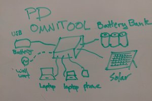
 Jaunty Wunderkind
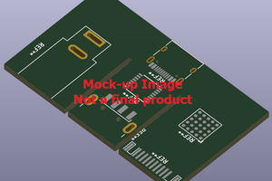
 Torbjörn Lindholm
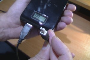
 Films4You
"65W / 100W Solar PD Regulator Module"
I am unable to access the taobao link you shared. I tried signing up but getting some or the other error. Can you share if the module is available on aliexpress or on some other site?