 Jon
JonIn the beginning ... there was darkness (metaphorically speaking)
When I finished my Home Assistant setup and I finished integrating all my Tuya lights, not just the ceiling ones, I realized that just turning them on/off wasn't going to be enough. By then, I chose the two-state Tuya controllers for most of my control systems, without knowing that a wonderful world of custom-made boards was waiting for me...
 I couldn't leave things like this, and I started thinking how what could be improved. Soon I found that my entrance furniture (with some ambient warm white lights) could use an upgrade to smoothly control the background illumination it projected.
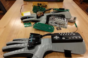
On the first draft of the Smart Lights board, I wanted it to have more functionalities behind just controlling some lights, it had to be my testing platform for some other sensors and devices that I was really wanting to play with.
One of the main ideas behind this first design (as I said, besides just controlling the entrance lights), was to make a customized alarm system that would turn on some red LED on the entrance furniture if I didn't successfully log in with my fingerprint after entering home. It was triggered through a hall sensor on the door entrance connected to one of the input pins of the board.
The sensor to perform my fingerprint identification was the R503 Capacitive Fingerprint Reader, plugged through a 6 pins 1mm pitch JST connector.
I had a 60 seconds window time since the system registered that I entered home until I got notified via the HA app (and some red LEDs illuminated the entrance) if nobody successfully scans their fingers.
 For simplicity reasons, I used ESPHome for all the firmware, and for the notifications automation Home Assistant.
As I wanted to arm the alarm easily before leaving and I had a couple of the Tuya Smart Switch remote controllers, operating on the 433MHz band, I also left a connection port on the board to mount a 433MHz RF link.
However, this device used to receive a lot of noise and I had to spend some time researching which filtering configuration to set in order to reduce the false armings of the alarm.
In addition, many times it didn't even receive the arm command (by just pressing the remote), and I had to press it several times until it recognized the command and armed the board...
This board, the Smart Lights, despite being an excellent testing platform for some devices, had some issues that I needed to fix, such as a poor layout distribution, with silkscreens too little to be read, or a lack of embedded pushbuttons.
It was a good starting point, but the naming was too specific for the purpose of the board, so I split the functionalities into two upcoming projects, the Smart Lights project and the Smart Alarm project (that will have its own post later):
- The Smart Lights X1: a small board capable of controlling one channel, where the size had to be the minimum as possible while keeping an elegant design.
- The Smart Lights X4: a bigger board capable of controlling up to 4 individual channels.
The Smart Lights X1
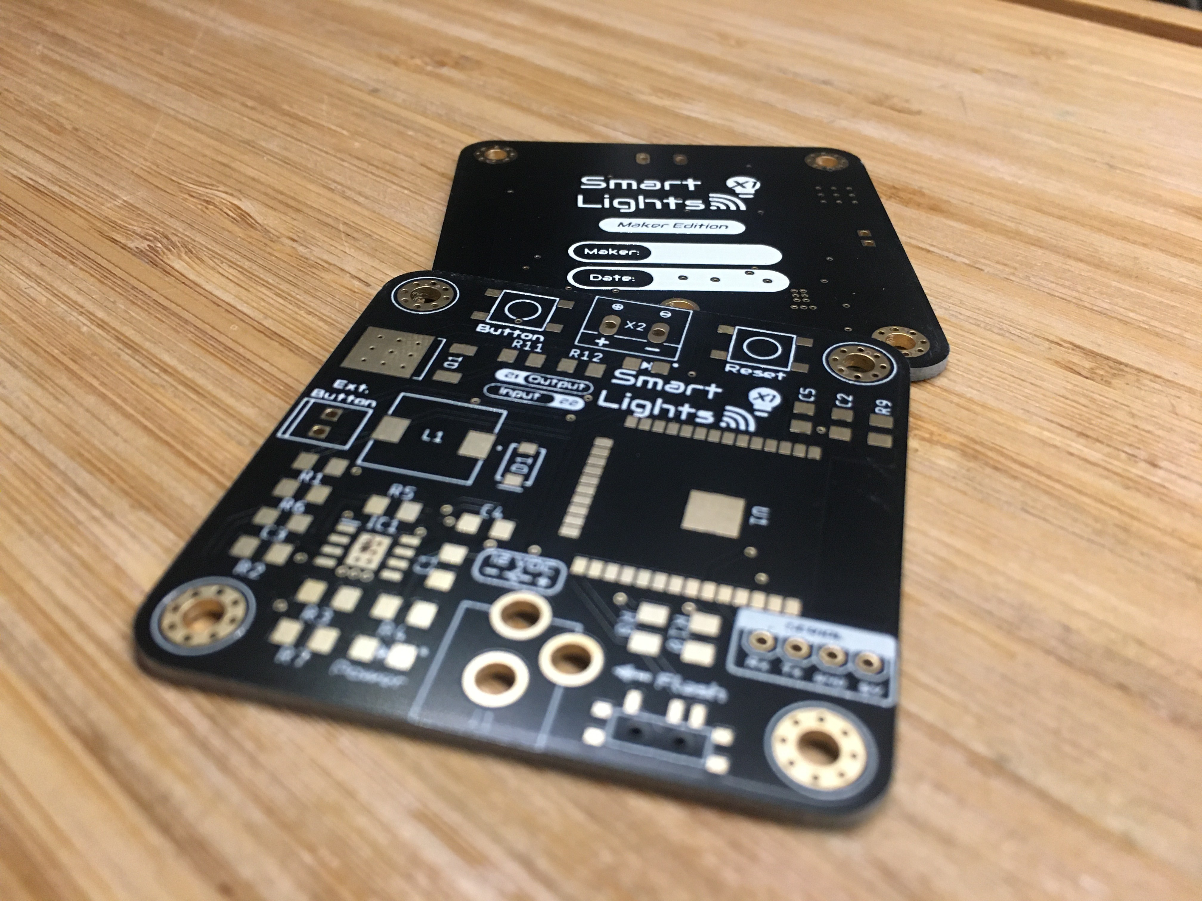 The main idea behind the X1 version was to be used as a teaching platform for a course I organized about electronic design with EAGLE: the course was intended to cover the full development of an electronic board oriented to IoT applications, from the schematic design to the programming.
As a part of the course, the attendants would receive a PCB (the Smart Lights X1 Maker's Edition) that would be assembled during the lesson, combining through-hole and SMD components (where the minimum size was 1206).
In further developments, I made a pre-assembled version of it, moving to smaller SMD components and ready to be programmed and used.
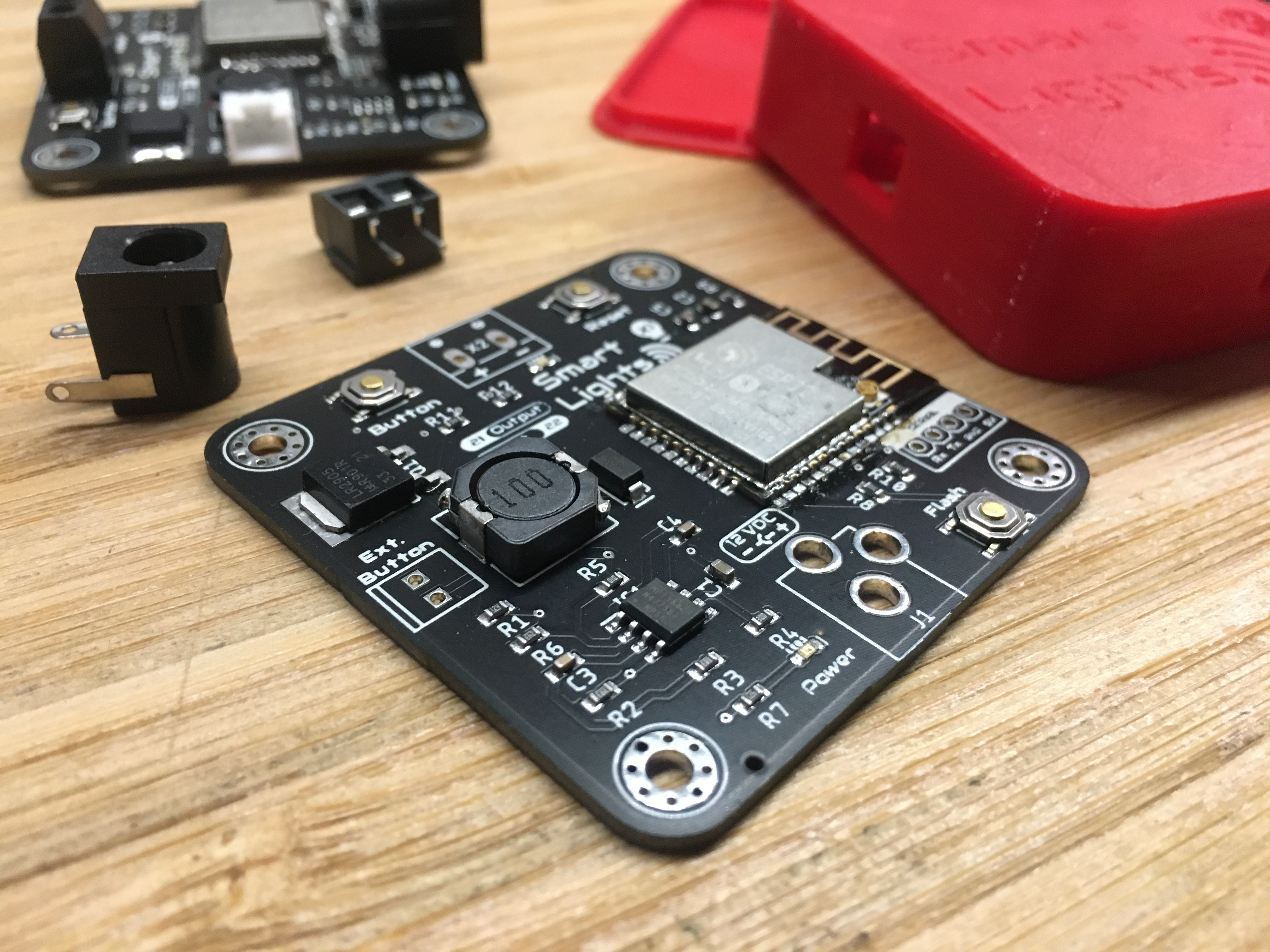 I also designed a 3d printable enclosure (Top + Bottom) and two small accessory pin buttons to press the...
 Nolan Moore
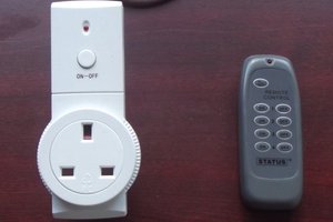
 Andy Smith
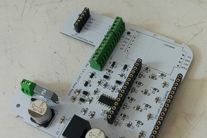
 Maya Posch
 Alvaro Ferrán Cifuentes