03/09/2023, 13:20, Sunday.
Well, I'm writing this² after finishing this project log because I feel like I failed this project log.
Even though I reached a few conclusions on how much energy I would require depending on the type of pump I used, I didn't reach any satisfactory conclusion.
Neither did I make any useful 3D model.
I will try again later and maybe this little message will be deleted, but still.
----------------------------------------------------------------------------------------------------------------------------------------------
So, I'm writting this here because I had some ideas for making a cheap DIY pump, my stupid brain simply insists that I'm simply not trying hard enough when there is simply no easy way of doing these kinds of things.
----------------------------------------------------------------------------------------------------------------------------------------------
Well, where do I start?
I was checking some other solenoid valves that aren't 5kg of force, and decided to at least give a try with the 25 newton solenoids.

This one weights 100 grams, but I would bet it is more likely because of the steel part rather than the copper coil.
In either way, you could use aluminium wire instead of copper, but it is a little bit cheaper per kg than copper.
Anyway, this one uses 4.8 watts of power, but in some sites it says it uses 30 watts.
So I thought on making a free piston/plunger with 7mm to 8mm of diameter (needing a force of 19 Newtons to 25 Newtons respectively) moving 50 times a second, it will be able to achieve 1.5 liters per minute in each side of the pump, so 3 liters per minute in total.
This would be able to more or less actuate two filament artificial muscles, however, if you braid those like intended, you would use longer muscles that in turn would need more fluid flow.
Now, for the working principle you have two options:
- Using a soft iron core with two coils that will alternatively pull the free piston torwards in alternating turns.
![]()
- Using a Neodymium magnet as the free piston with a single coil that will change the electromagnetic poles, making the magnet move up or down.
![]()

Both have advantages and disadvantages, but let's remember that this thing will be moving 50 times a second, I'm confident the iron core can handle it, but I don't know about the neodymium magnet.
In both cases you will need a way of knowing where the free piston is, using some kind of sensor.
First I thought on using a hall sensor or a mechanical switch, but the hall sensor has to take into consideration the electromagnetic field and the mechanical switch has to take into consideration the pressure inside the chamber, so it doesn't activate with the pressure.
I'm pretty sure there is a easier way of doing that, but I couldn't think of anything.
With a 1kg of copper and 100gram coil per solenoid pump consuming around 30 watts of power, you would be able to power 20 muscles, or in the worst case, 10 muscles.
Since 1kg of copper wire is 100 reais (20 dollars), you would use 1500 to 3000 reais (300 to 600 dollars) in total. Not so dissimilar than the 10 dollar brushless motor.
But the downside of the brushless motor is that it needs a reduction gear and a very bulky hydraulic gear pump.
Now, about the hydraulic gear pump and/or the axial piston pump.
One thing I was very clear on talking about was the precision between the parts, which I don't really think it would be easier (or possible) to do in a DIY way.
The idea would be to simply do two things:
- Using a glass plate with abrasive material on it.
- And/or using a DIY lathe.
The glass is the flatest surface that one could have at home, so by using it like a "sand paper", you could achieve incredibly flat surfaces.
In this video the guy does something similar, at the 6 minute mark.
This will be useful both for the axial piston pump and gear pump.


However, as you can see, both pumps have round surfaces, either with the gear teeth and/or with the piston heads.
In such cases, you will need to use a DIY lathe with a drill or something like that, there are plenty of 3D printable lathes on thingiverse and other similar websites.
However, the idea here is to 3D print either pump with a overhang in both cases and sand it down using both methods, and after that, use the sanded 3D printed parts to make a mold, and finally, make a copy using resin or molten plastic.
In the case of the gear pump, I think it would be harder to sand down the gear teeth, whily the axial piston pump would probably be the easiest to DIY.
By the way, you can easily find a lot of gear pump and axial pump 3D models on thingiverse and grabcad.
Although you have to pay attention to their description in order to know if it is a mockup or a super detailed and/or functional 3D model/3D print.
I don't even know why I'm doing this Project Log, like I said in the project details. I really can't keep up with this project, but my mind simply says that I'm not trying hard enough even though I gave my best...
One would need one of these DC power supplies in order to test it out, but I don't have money for them.
One would need to buy 1kg of copper wire or enamelled aluminium wire, but I don't have money for that either.
In resume, I'm broke as hell, and the only way I would be able to continue this project is if I had any.
In either way, I'm trying to find an equivalent for the tiny brushless motor's hydraulic pump.
The Samguk Series brushless motors have a maximum RPM of 30,000, but hydraulic pumps normally operate at maximum 2500 to 3000 RPM with a minimum of 0.8 Nm to 2 Nm.
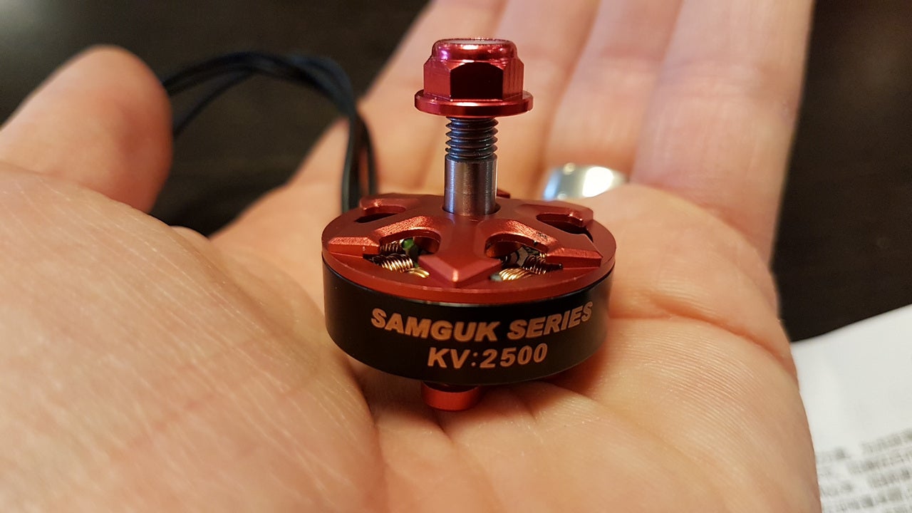
The idea would be to have a hydraulic pump that can directly be mounted to such small motor with such rpm.
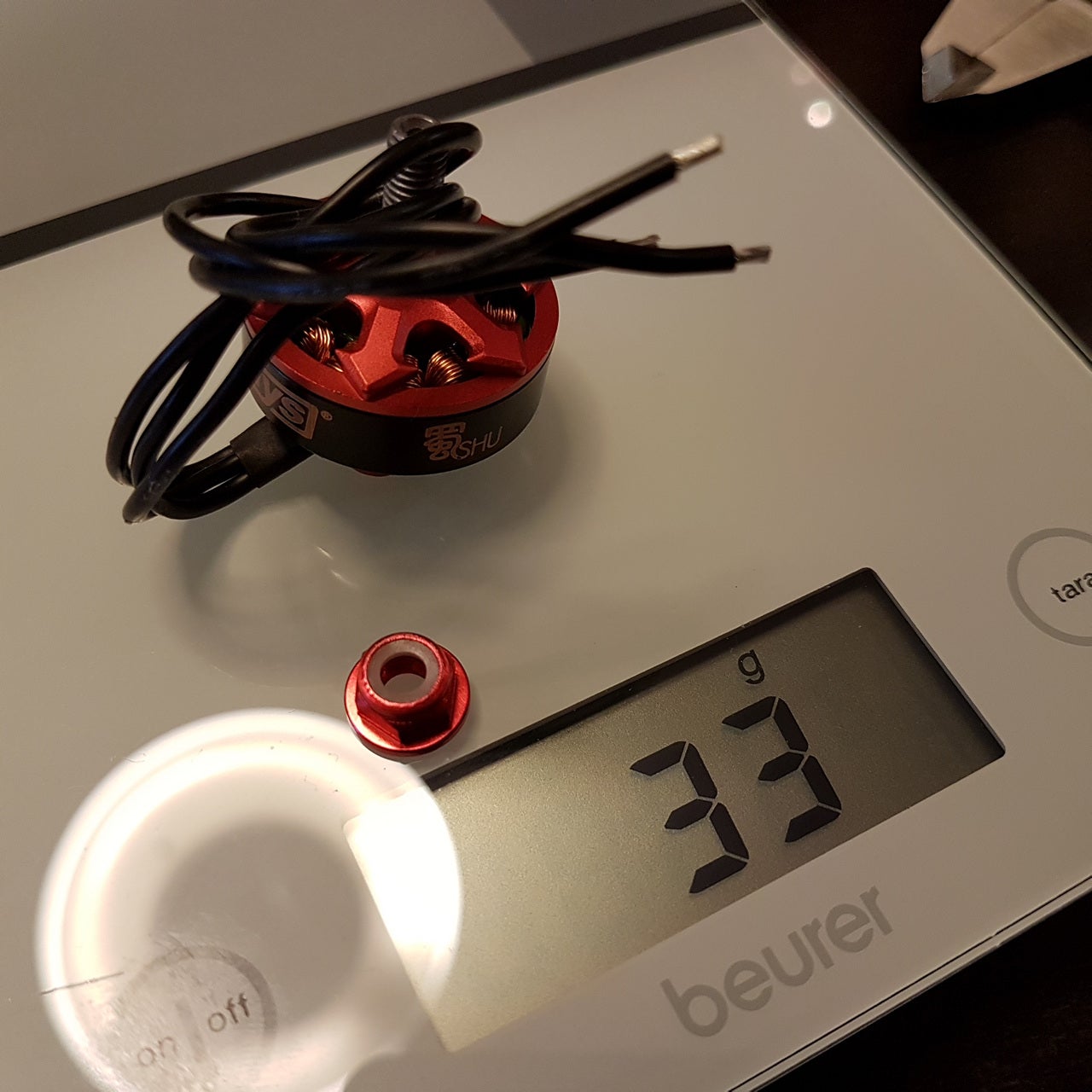
The best I first thought was to make a solenoid pump, but these aren't as efficient and are heavier than the aforementioned brushless motor. Such motor only weights around 50 grams and outputs 750 to 900 watts of power, while the solenoid itself can weight around 100 to 200 grams and only output a maximum 30 watts.
The motor would be able to supply 10 muscle filaments at same time (if connected to a gear pump and a reduction stage) while the solenoid pump can only fulfill only 1 to 2 muscles.
Obviously, one should take care of cavitations at such high rpm. But if the pump is as small as the motor, I don't think it would be much trouble.
Again, I THINK, this is not a good indication to begin with.
Anyway, I tried to calculate:
Basically, I know I want to make a 5 to 6 piston axial pump, and that it would rotate 500 times a second, giving 30k RPM.
So:
500 * 5 * 60 * x = 20,000 mL per minute.
x = (20,000/150,000)
x = 0.13333333333
So, each piston will need to have a 0.13333333 milliliter displacement.
And accordingly to the pipe volume calculator, I would need a 5mm diameter bore/piston with a travel of 6.79mm.
And in turn, the entire axial piston pump would need to be something with around 48.62794mm of diameter or less in order to achieve 5 bar of pressure with the Samguk torque of 0.2387 Nm.
But since there will be 5 piston heads, and 2 to 3 will be travelling downards, does this mean that it will need 2 to 3 times the force? If so, it would need to be 26.5222mm to 17.68148mm in diameter.
Oh yeah, I forgot, the 0.2 Nm is the torque when the electric motor will be at maximum wattage (750 watts), but since it needs to work at +/- 300 watts, it would need half of that diameter, so 13.2611 mm.
But this value is so small that I don't think the piston heads would even fit inside of it, I think it would be better to actually cut by half the diameter of the pistons to 2.5mm and simply double its travel to 13.58mm.
The diameter of a piston pump is more or less the distance of travel, so the radius and the stroke are pretty close, which is a positive sign.
Now I have to stop procrastinating from making the exoskeleton and the hydraulic pump at same time...
Well, I tried to make the axial piston pump on blender with these parameters, but it seems this specific pump is way too complicated for my limited knowledge in 3D modelling...
You can still take the first piston pump I made earlier and just scale it down, but heh, we are talking about a piston with 2.5mm of diameter, it wouldn't be worth the trouble even if it was possible to 3D print such thing.
Accordingly to this piston speed calculator, the piston would be travelling more or less 6.79m/s when pulling the fluid.
But I don't know if this will be enough to create cavitations tho.
I would assume that it wouldn't, simply because cavitations are caused by vacuum, and the bigger the surface area, the stronger the vacuum, since this is so small, even if cavitations occurred, they wouldn't be as destructive as in conventional pumps.
This is a rough guess made by a person that doesn't know anything about hydraulics.
Also, I was wondering, even with a pump proportional to the brushless motor, there is still the problem of actually reaching the appropriate speeds.
For example, I found this old video about preloaded artificial muscles here on hackaday and it takes an awful lot to fill each opposite muscles:
Obviously, I'm not trying to insult or demean anyone, but a lot of DIY attempts focuses on doing the stuff rather than trying to think on how well the stuff does certain job.
The person uses a RC hydraulic pump, which can achieve 100 bar (10 Mpa) of pressure, but only has 1 to 2 liters per minute of fluid flow, which can be responsible of such slow actuation.
Also², I was searching for articles about untethered artificial muscles (again), just because I know a thing or two more than I did before.
For example, I remember seeing one which used a heating element to heat up paraffin and expand the muscle, but it took literal minutes to do so. If I were to accelerate such process, I would need to make hundreds or even thousands of super thin paraffin muscle filaments


This one uses one of those electromagnetic heaters, which takes 3000 watts to work.
In both cases it would be better to simply use silicon carbide powder in both cases and a microwave source, just like I talked on previous project log.
But in either case I don't think the materials would survive very longer under such extreme heat, it will be maximum 100ºC in the case of water, but still, we are talking about a thin layer of plastic.
Maybe one could use ethanol, perhaps? "Just" heat-muscles with flamable fluids, what could go wrong?
Also, something that I didn't talk about in the previous project log was the idea of adding a water spray system to Shape Memory Alloy/Polymer muscles in order to achieve rapid cooling, which would also be useful in this specific case.
Although I don't know how well this system would work with a high frequency actuation, like when you are running, for example.
In such case, how do you get rid of the fluid?
"Simply" spraying cold air would be interesting, but air has a terrible heat conducting, unlike fluids.
I don't know why I would want a mech/exosuit to run very fast, but I can see a slower one being used for heavier loads.
Maybe I should give up on a fast moving mech/exosuit and stick with something simpler.
A thermal McKibben filament artificial muscle would be way easier to mass produce and assemble than a hydraulic one with hundreds of filaments and even more hydraulic pumps and brushless motors.
... But it would create another problem, the problem of efficiency...
... And I also don't know how well I could calculate and predict their actuation before even making them myself...
I asked to ChatGPT and it said that the energy conversion of silicon carbide powder in turning electricity to heat is around 90%, although I don't know its efficiency of microwave to heat conversion (I'm waiting for answers in other websites).
I can in turn take the energy required to heat up an "X" grams of silicon carbide to a "Y" degrees and then see how much energy one needs to heat up an "Z" grams/ml of a certain liquid to "W" degrees, and finally, how many "V" ml/liters of gas these "Z" ml of liquid would produce, and thus, how much pressure it would apply inside the McKibben muscles.
Not so dissimilar from calculating how much energy one needs to input in order to boil water (aka Calories).
Then I would need to approximate how many liters of water I would need to spray on the muscle bundle in order to absorb this X amount of heat.
Even if the efficiency of the Silicon Carbide powder to heat is 90% and the efficiency of liquid to gas is also 90%, the water pump and the heat exchanger will diminish the overrall efficiency of the system.
In either way, I'm starting to wonder how in tarnation I would make the silicon carbide heating element for this muscle.
I doubt I could simply add silicon carbide powder to a liquid, pass an electrical current through it and everything will heat as expected.
I think one would need to make DIY heating elements by either making a DIY conductive ink but with silicon carbide or making a semiconductive filament with silicon carbide powder.
During the video (+/- 1:40 min mark) the guy explains how to calculate how much electricity would be required to generate an X amount of heat.
Which makes me wonder how I'm going to deal with the heat conduction of each material, since the cooling system (and thus, the diactivation system) is on the outside. I would need to either make reeeally thin McKibben muscles and/or use highly thermally conductive materials, like copper and/or aluminium.
Which² would also increase the chances of ending up having short-circuits all over the place, since said materials are also electrically conductive.
Which³ would also increase the difficulty of production and weight, plastics are easier enough to melt together in a tubular shape (or you can already buy something with a tubular shape), but metal foils on the other hand...
Maybe I could put a liquid spray inside the muscle so it condenses the vapour back to its liquid form, but I would be dealing either with water or ethanol, and both are not so ideal options.
Water needs to much energy to boil/vaporize, but ethanol is flamable...
... The more I think of it, the more I think it is not a good idea overrall...
Well, I was kinda lazy, but I think I have all the necessary information for calculating these new muscles.
So, 1 calorie is a unit of energy required to heat 1 gram of water to 1ºC at room pressure.
Is useful to remember that the boiling temperature of water increases with the pressure, so the bigger the pressure inside of the artificial muscle, the more energy I would require to vaporize water.
So, inside a 1 inch diameter muscle with 30cm of length, there are 0.152 liters, or 152 grams of water at room temperature.
Assuming that room temperature is 27 ºC, I would need to add 73ºC of heat to the water to 100ºC, so 152x73 = 11096 calories.
This is more or less 12,8 watt-hours.
However, at 5 atm (or 5 bar), the boiling pressure of water is around 151ºC.
152x124 = 18848 calories = 21.9 watt-hours.
Of course, this is a calculation with perfect heat transfer and perfect conversion to water vapour. Which is not possible.
(By the way, I would need to use silicone rubber or polyurethane as the inner bladder since now the temperature is so high)
Now, I need to find how much ml of water I would need to boil from that 152 ml of water in order to achieve 5 bar of pressuree inside the muscle.
"Steam is a specific kind of vapor that is only produced through boiling. And when steam is created, it also expands. Each liter of water that is boiled will expand to 1600 liters of steam!"
Source: https://tuttnauer.com/blog/autoclave-sterilization/basic-concepts-of-steam#:~:text=Steam%20is%20a%20specific%20kind,to%201600%20liters%20of%20steam!
Well, since 1 liter = 1600 liters of steam, in order to make 0.152 liters 5 times to achieve 5 bar/atm of pressure, I would need 0.76 liters of steam...
So I would need to divide 0.152 liters by 1600 liters of steam? I'm a little bit confused.
0.152/1600 = 0.000095 x 5 bar = 0.000475 liters
I asked ChatGPT, I think he got it right:
"To determine how many liters of water you would need to produce 0.76 liters of steam, you can use the given ratio:
1 liter of water produces 1600 liters of steam.
You want to find out how much water is needed to produce 0.76 liters of steam. You can set up a proportion to solve for it:
(1 liter of water) / (1600 liters of steam) = (x liters of water) / (0.76 liters of steam)
Now, you can cross-multiply and solve for x:
1 * 0.76 = 1600 * x
0.76 = 1600x
Now, divide both sides by 1600 to isolate x:
x = 0.76 / 1600
x ≈ 0.000475 liters of water
So, you would need approximately 0.000475 liters (or about 0.475 milliliters) of water to produce 0.76 liters of steam at room pressure according to the given ratio."
So, since to heat 1 gram of water in 1ºC I would need 1 calorie, this means that in order to heat 0.475 milliliters (or 0.475 grams) of water, I woudl need...
0.475x124 = 58.9 calories = 0,06845489 watt-hour of energy.
Well, I don't know how incorrect I am, but this... Looks too much too little. lol
You telling me in order to make an 100kg rated artificial muscle to achieve 5 bar of pressure, I would just need 0.06 watts?!
I asked this around and someone said to me I should give a look at "the latent heat of vaporization" of water.
"For example, the latent heat of vaporization of water is 540 cal/g and the latent heat of freezing of water is 80 cal/g. Therefore, changing a given quantity of water to steam requires 5.4 times as much heat as warming it from 0°C (+32°F) to 100°C (212°F), and melting ice requires as much heat as warming water from 20°C (68°F) to 100°C."
Source: https://byjus.com/physics/latent-heat-of-water/#:~:text=For%20example%2C%20the%20latent%20heat,water%20is%2080%20cal%2Fg.
So, I don't know which value to take from this, 5.4 or 540.
In either way:
0.475x124 = 58.9 x 5.4 = 318.06 calories = 0,369587 watt-hour.
0.475x124x540 = 31806 calories = 36,9 watt-hour.
If I use both values:
0.475x124x540x5.4 = 171752.4 calories = 1996,1 watts.
Well, now this sounds more right, I guess...
When water converts from a liquid to a gas, a quantity of heat energy known as the latent heat of vaporization is required to break the hydrogen bonds. At 100 °C, 540 calories per gram of water are needed to convert one gram of liquid water to one gram of water vapour under normal pressure.
Water can evaporate at temperatures below the boiling point, and ice can evaporate into a gas without first melting, in a process called sublimation. Evaporation below 100 °C and sublimation require more energy per gram than 540 calories. At 20 °C (68 °F) about 585 calories are required to vaporize one gram of water. When water vapour condenses back to liquid water, the latent heat of vaporization is liberated. The evaporation of water from Earth’s surface and its condensation in the atmosphere constitute the single most important way that heat from Earth’s surface is transferred to the atmosphere. This process is the source of the power that drives hurricanes and a principal mechanism for cooling the surface of the oceans. The latent heat of vaporization of water is the highest of all common substances.
Source: https://www.britannica.com/science/seawater/Thermal-properties
So, if I understood this right (which I may probably be wrong), since 540 is 5.4 times more energy per gram of water, this means that I need 100 calories, then after that, I would need to multiply by 5.4 for every degree?
So, let's say that I need to heat up the water to 200 degrees, since 150ºC is already the limit due to the 5 bar of pressure parameter.
I would need 50 calories x 5.4 = 270 calories + 58.9 calories = 328.9 calories = 0,38 watt-hour.
I don't understand, I'm on the right track?
I asked ChatGPT because nobody is being able to answer me:
"Your calculations are on the right track, but there are some nuances in your understanding of the thermodynamics involved in heating water and converting it into steam that need to be clarified.
First, the latent heat of vaporization for water is indeed about 540 calories per gram (or 540 cal/g). This means that to convert 1 gram of liquid water at 100°C to 1 gram of steam, you need 540 calories of energy. This value is constant, regardless of the initial temperature of the water.
However, when you're dealing with changing the temperature of water from a lower temperature to a higher temperature, you need to consider the specific heat capacity of water. The specific heat capacity of water is about 1 calorie per gram per degree Celsius (1 cal/g°C). This means that to raise the temperature of 1 gram of water by 1 degree Celsius, you need 1 calorie of energy.
Now, let's break down your calculation for heating water to 200 degrees Celsius:
- To heat 0.475 grams of water from 27°C to 100°C:
- ΔT (temperature change) = 100°C - 27°C = 73°C
- Energy required = mass (0.475 g) x specific heat capacity (1 cal/g°C) x ΔT (73°C) = 34.675 calories
- To convert 0.475 grams of water at 100°C to steam:
- Energy required = mass (0.475 g) x latent heat of vaporization (540 cal/g) = 256.5 calories
- To heat 0.475 grams of steam from 100°C to 150°C (assuming the 5-bar pressure limit):
- ΔT (temperature change) = 150°C - 100°C = 50°C
- Energy required = mass (0.475 g) x specific heat capacity (1 cal/g°C) x ΔT (50°C) = 23.75 calories
So, the total energy required to achieve your desired conditions is approximately 315.925 calories, which is approximately 0.367 watt-hours. This calculation takes into account both heating the water and converting it into steam.
You can see that this value is relatively close to your last calculation, which is a good sign that your approach is reasonable. The key is to correctly account for the energy needed to heat the water to the desired temperature and the energy needed for the phase change from liquid to steam.
Keep in mind that these calculations are idealized and do not account for losses due to inefficiencies, so in practice, you may need to provide slightly more energy to achieve the desired result."
To calculate the energy required to transform 1 gram of water into steam, you need to consider the specific heat of water and the heat of vaporization of water.
- Specific Heat of Water (C_w): The specific heat of water is the amount of energy required to raise the temperature of 1 gram of water by 1 degree Celsius. It is approximately 4.184 joules per gram per degree Celsius (J/g°C).
- Heat of Vaporization of Water (H_vap): The heat of vaporization is the amount of energy required to transform 1 gram of water at its boiling point into steam without changing its temperature. It is approximately 2260 joules per gram (J/g).
Now, to calculate the energy required to transform 1 gram of water into steam at its boiling point:
Energy (in joules) = Mass (in grams) x Specific Heat (J/g°C) x Temperature Change (in °C) + Heat of Vaporization (J/g)
In this case, the temperature change is from the boiling point of water (100°C) to the boiling point of steam (100°C). So, the temperature change is 0°C because the temperature remains constant during phase change.
Energy (in joules) = 1 gram x 4.184 J/g°C x 0°C + 2260 J/g Energy (in joules) = 0 + 2260 J
Now, to convert joules to watt-hours (Wh), you can use the following conversion:
1 joule = 0.000277777778 watt-hours (Wh)
So, to convert the energy from joules to watt-hours:
Energy (in Wh) = 2260 J x 0.000277777778 Wh/J Energy (in Wh) ≈ 0.627 Wh
So, it takes approximately 0.627 watt-hours to transform 1 gram of water into steam at its boiling point.
Since I'm dealing with 3 grams of water, then I would need 0.29 watt-hour.
I mean, 0.1 gram = 0.0627 watt hour, since I'm going to need 4.75 times more.
So 0.0627x4.75 = 0.297825 watt-hour.
Unfortunately, I can't find an answer anywhere, so this value that ChatGPT found is the "best" answer we have for now.
And even then, it gives totally different results whenever I ask it the same queston.
One time is 11 kilowatts, other time is 0.6 watt-hours, another 2 kilowatts...
I received an answer:
You need to specify the initial temperature of the water. Although the vaporization phase requires most of the energy, so you won’t make a big error if you don’t specify it.
First, find the energy needed. There are two steps in the process: raise the temperature of the water to the boiling point, then vaporize the water.
To find the energy needed to raise the temperature, use the specific heat of water. c = 4.184 J/g•K. Then Q1 = m•c•delta-T. Assuming the water starts at room temperature, 20˚C, and must be raised to the boiling point, 100˚C, this gives Q1 = (1 g)(4.184 J/g•K)(100˚C - 20˚C) = 335 J. Note that the size of the K and the ˚C are the same, so they cancel.
To find the energy needed to vaporize the water, use the heat of vaporization. L = 2260 J/g. Then Q2 = mL = (1 g)•(2260 J/g) = 2260 J.
The total energy needed to heat and vaporize the water is Q = Q1 + Q2 = 2595 J.
The Watt-hour is a unit of energy. 1 Watt = 1 J/s, so 1 Watt-hour is 3600 J. So Q is already a quantity you can express in Watt-hours: Q = (2595 J)/(3600 J/Watt•hour) =0.72 Watt•hour.
If you want to deliver this energy in 1/5 = 0.20 s, the power you’d need is P = Q/t = (2595 J)/(0.2 s) = 12,975 J/s = 12,975 Watt.
Well, this is not efficient, I suppose...
----------------------------------------------------------------------------------------------------------------------------------------------
Also³ I just found this video of a soft pump:
Here is how the pump is made:
It makes me wonder why they didn't simply took a polyurethane/TPU tube and skiped half the work...
Source: https://www.science.org/doi/abs/10.1126/science.ade8654
It is pay per view and I can't find anywhere else, so I don't know its efficiency, the voltage required and so on.
In the video it shows a graphic with it achieving 8 kilovolts maximum, but still, I don't know the exact amperage and the efficiency of the system.
In the video there is the amperage and the voltage in a graphic.
So it has 5 microamps and 5 kilovolts, so it uses 0.25 watts in total.
0.000050x5000 = 0.25
I'm not very smort, the description of the video has a website and in that website there is a link to a free version of the manuscript:
https://www.science.org/stoken/author-tokens/ST-1105/full
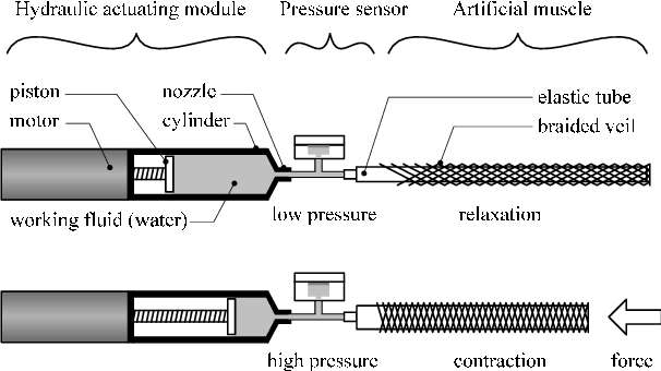
Incorporating pressurized fluidic circuits into textiles can enable muscular support, thermoregulation, and haptic feedback in a convenient wearable form factor. However, conventional rigid pumps, with their associated noise and vibration, are unsuitable for most wearables. We report fluidic pumps in the form of stretchable fibers. This allows pressure sources to be integrated directly into textiles, enabling untethered wearable fluidics. Our pumps consist of continuous helical electrodes embedded within the walls of thin elastomer tubing and generate pressure silently through charge-injection electrohydrodynamics.
Each meter of fiber generates 100 kilopascals of pressure, and flow rates approaching 55 milliliters per minute are possible, which is equivalent to a power density of 15 watts per kilogram. The benefits in design freedom are considerable, which we illustrate with demonstrations of wearable haptics, mechanically active fabrics, and thermoregulatory textiles.
100 kilopascals = 1 bar of pressure.
55 ml per minute = 0.055 liters per minute.
If the artificial muscle is a 12,5mm inner diameter and 30cm of length, then it will need more or less 1.8 liters per minute, if it is a 1 inch inner diameter with 30cm of length, it will need 8.1 liters per minute.
I would need 5 times more pressure and 32.7 times more fluid flow in the filament case and 147.2 times in the 1 inch case.
I don't really know how to increase the pressure, but I would suppose that in order to increase the fluid flow I would need to increase the number of flexible pumps... By 32.7 times...
If I were to increase the pressure by 5 times and fluid flow by 32.7 times, I would need:
0.25x5x32.7 = 40.875 watts
Well, a little less efficient than the hydraulic pump with the brushless motor, which would consume 300 watts for 10 muscles, so 30 watts for every muscle.
Now, I "just" need to figure out how to increase the pressure and fluid flow...
It says "each meter", does this means that I need to increase the meter of the pump to increase the pressure? Or that I need to increase the amperage?
I just woke up, I will try to read the rest of the paper later...
Anyway, I'm trying to get a grasp on the subject, but I'm failing miserably.

In the "B(i)" graph, it shows how the max pressure lowers based on the increase in diameter of the tube, but increases the flow rate.
On the "C" and "D" graph, it shows how the pressure and flow rate increases with the length of the pump.
Which makes me wonder if in order to increase both pressure and flow rate I only need to increase the length...
I'm sending an email to the authors, I doubt I will receive any answer...
But I would bet that in order to achieve the desired flow rate I would need to put various parallel pumps, now, for the pressure...
I received an answer, and the authors said that they never tested the pump with these parameters, but said that I'm probably right that increasing the number of pumps in parallel and the length would increase the fluid flow and the pressure.
-------------
Also, in other images it shows that the copper electrodes are in direct contact with the fluid, which explains why they didn't simply glued the copper wires to the outside of a TPU (thermoplastic polyurethane) tube.

However, one could still buy a TPU tube, open it up, insert the rod with the copper electrodes inside it, remelt it in order to close the tube again and "glue" the electrodes to the inner walls.
The fiber pumps can pump continuously for up to 6 days before chemical deposits passivate the electrodes (fig. S7H). This is considerably longer than any other reported EHD pump, soft or otherwise (9), and can likely be improved further through careful selection of liquid and electrode material.
ffffffff- ok, how do I increase this value?
Edit¹: (12/01/2024)
This is me from the future.
One thing that I didn't learn until later on is that electrostatic currents can pass through anything, even thin wires with a lot of resistance.
In fact, you could replace the copper wires by conductive ink just fine (which puts into question on why go the trouble the guy went to use TPU and copper wires).
In fact², you could easily 3D print the entire pump in a compact manner for somewhat cheap.
I also made the calculation, you would need 5 meters for 5 bars of pressure and 219 parallel tubes for a fluid flow of 12 liters per minute.
If you have a 10 cm long reverse piston with 25mm of diameter (1 inch), you would be able to lift 25 kilograms, which would mean 2.2 watts per kilogram.
This is assuming 5,000 volts and the only 4 electrodes per tube, by increasing the length and the quantity of electrodes, maybe the amount of wattage will change. But again, I can't test that. I'm broke.
Of course, the bigger the flow rate, the bigger the energy required. So if you increase the velocity of actuation, it will consume more energy momentarily.
-----------------------------------------------------------------------------------------------------------------------------------------------
To extend the operational lifespan of the fiber pumps and delay the passivation of the copper electrodes, you can consider alternative materials for both the electrodes and the working fluid. Here are some material options to consider:
1. Electrode Materials:
- Platinum or Gold: These noble metals are highly resistant to corrosion and can withstand prolonged exposure to the working fluid. However, they are more expensive than copper.
- Carbon Nanotubes: Conductive materials like carbon nanotubes can be used as electrodes. They have excellent chemical stability and durability.
- Graphene: Similar to carbon nanotubes, graphene is chemically stable and can be used as an alternative electrode material.
- Titanium: Titanium and its alloys are known for their corrosion resistance. They may be suitable for long-term exposure to certain fluids.
2. Working Fluids:
- Ionic Liquids: Ionic liquids have low volatility and are known for their chemical stability. They can serve as a suitable dielectric fluid in EHD systems.
- Fluorinated Fluids: Fluorinated fluids, like perfluorinated compounds, are often used as dielectric fluids due to their high breakdown voltage and chemical inertness.
- Silicone Oils: Certain silicone oils have good dielectric properties and are chemically stable, making them a potential choice for the working fluid.
- Custom Formulations: Depending on the specific application, you might consider formulating a custom dielectric fluid with additives to improve stability and reduce the likelihood of passivation.
It's essential to assess the compatibility of the chosen materials with the specific requirements of your wearable fluidic system. Factors such as electrical conductivity, dielectric properties, chemical compatibility, and cost should all be taken into account when selecting alternative materials. Additionally, long-term testing and monitoring can help evaluate the performance and stability of the chosen materials over extended periods to ensure they meet your desired lifespan requirements.
"Throughout this work, we used the dielectric liquid Novec 7100 (3M). This is a nontoxic, nonflammable methoxy-fluorocarbon with low global warming potential (20). It is commonly used as a solvent and for heat management but also performs well as an EHD fluid because of readily ionizable fluorine groups and a high electrical breakdown field of 10 kV/mm (20). Other liquids (including nonfluorinated compounds) may be pumped, provided that they have low conductivity and viscosity and are electrochemically stable (21, 22)."
I tried to look around and see if I could find this liquid, and boi, oh boi.
I kid you not, 3 liters of this fluid costs 16,000 reais (3,200 dollars).

Also, I just found this other link were it "only" costs 11,000 reais (2,200 dollars) and weights around 15kg:
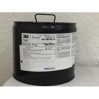
This is more or less 1000 reais (200 dollars) per kg of fluid.
Of course, the paragraph says that other dieletric fluids may be used, but oh boi, what are the other dielectric fluids?
When it comes to dieletric stuff I don't know a hint.
Well, anyway, unless I can actually test the goddamn filament pump by myself, I can't know for sure how many of those I would need.
And in order to test that, I need money, which in matter of money, I don't have any.
In any matter, if I can simply increase the fluid flow and pressure of the pump by increasing the length of the pump, then it will probably not be worth the trouble.
We are talking about a 1 meter long (1000mm long) pump that can output only a few ml per minute and 1 bar of pressure.
If I were to increase its length 1 time per bar of pressure, I would need more or less 5 meters of tubing with copper or titanium electrodes for every 30cm long muscle.
I would already need kilometers for the bladders of the artificial muscles, just imagine how much TPU I would need...
If I can increase the pressure and fluid flow by simply increasing the voltage and amperage, I would still need 1 meter of tubing per 30cm of muscle.
I just found this video about electroosmotic pumps.
It uses 200 volts and 0.0022 amps, which translates to 0.44 watts.
The guy gives a way better and precise explanation, but basically, if you put two steel electrodes through a filter made out of glass in non-conductive water and pass a current through them, the water will flow to the negative electrode.
This is more or less the same principle the fiber pump I talked about before uses, but I don't know how much fluid flow I would get out of this system.
In fact, I don't even know how much fluid flow and pressure this system can output.
I couldn't even find a filter similar to the one used in the video.
I just found it, it is a fritter glass filter, and it costs around 130 reais (26 dollars) for every 10 units.
If this pump is capable of 5 bar of pressure and a fluid flow of 2 to 6 liters per minute, it would be really great for this project.
Even if it is not as efficient as a proper hydraulic pump, it is a system with no moving parts without expensive materials.
Until now, the problem is always the fact that I need an electric motor driving a pump, and both are expensive as heck.
A dielectric pump would be the ideal pump for this project, but alas, I don't know crap about these. And I can't find any accessible information on the subject...
I did found this graph for the electroosmotic pump:

This is a micropump, and assuming that the graph scales linearly (which doesn't), I would need... 3.3 times more voltage (around 660 V) to achieve 500 kpa and 23 ml of fluid flow.
Assuming that this uses the same amount of amperage, I would consume 1.46 watts of power.
If I need to increase the amperage, maybe I could increase the fluid flow or pressure...
But I don't know, I need to test it...
... But again, I don't have the money to buy the equipment...
I'm writing this just for the record, if I were to reach 6 to 10 liters per minute, I would need more or less 260 times more fluid flow, which I don't know if is affected by the voltage or amperage.
Either way, assuming that 1.46 watts is just to achieve the pressure and the 260x is to achieve the fluid flow, I would need 379.6 watts of power to achieve 7 liters per minute and 5 bars of pressure that would allow 10kg of force.
This means that I'm expending 37 watts per kg of force.
25 times less efficient than using a brushless motor with a hydraulic pump, but since both of these are extremely expensive and bulky, the best option is still the electroosmotic pump.
Actually, if it is an actuator with 25mm of inner diameter and a shaft of 5mm of diameter, I would need 10 liters per minute and just 2 bars of pressure to reach 10kg of force.
Now that I'm under the pressure thresshold, I don't know how well it would increase in fluid flow...
Since I need 10,000 ml per minute, I would need 1250 times more fluid flow (10,000/8 ml = 1250), so... Assuming that the amperage is the same, I would need 550 watts in total. For 10kg.
... I really don't know how well the pressure and fluid flow would scale up based on the voltage and amperage, but I would still prefer this method over using pumps and electric motors.
For the record² I thought on something interesting for this pump.
Basically, the idea would be to use the glass filter itself as the piston head for the hydraulic actuator, so the actuator could be self-contained.
(I could also use a brushless motor with propellers so it pushes the water down, moving up, but I think this method is kinda stupid, lol)
However, the question is how the heck you would keep everything together and how strong are these fritted glass filters.
Not to mention that no fritted glass will be in the exact size/shape you want...
Dunno if you would be able to simply cut them into shape tho...
Of course, assuming that I need to use fritted glass filters.
The dielectric fiber pump didn't need no filters, and maybe non-conductive membranes such as polyethylene separators for car-batteries could be used (the guy in the video about electro-osmosis said that "it can use most materials, even plastic" in its pump).
... But I don't know if either fritted glass or polyethylene separators are ideal for such task simply because it is too much of fluid flow to pass through microscopic channels, maybe I would need to make holes on polyethylene or glass in order to reach such fluid flows.
... But the pressure would be lowered a lot...
I know that bigger fluid flow equals lower pressures and that the relation between pressure and fluid flow is the same as torque and rpm, however, in this case, the lower the pressure, the more fluid I need in the system, and thus, more weight.
Again, I need to test it myself (or find a video of such test), and for that, I need, well, money.
I was thinking here, maybe I could use dielectric elastomers as the pump...
I didn't want to use dielectric elastomers artificial muscles because they seem too complex to mass produce in a DIY setup, but maybe I could make dielectric elastomer pumps.
These pumps would have no mechanical parts and be relatively simple to build...
... But it runs in the problem that I need to find a way of calculating them and the problem of efficiency...
I keep forgeting that this "little conundrum" isn't just a little conundrum, this is a literal barrier that much more knowledgeable professionals around the world are trying night and day to overcome.
I doubt a feeble minded fool such as myself to literally go against all odds and find a solution first.

This will be me, 40 years in the future and still wasting my time with this stupid project...
I still think the simplest hydraulic pump (besides the dielectric ones) would be the linear pump: an actuator pushing a syringe.
The muscle only need 0.006 liters in a 1/5 of a second after all.
I could literally stack 10 artificial muscles (which can lift 100 kg) and only use a 60ml syringe and a small linear actuator.
(However, assuming that the muscle contracts 20% of its length and increases diameter 40%, it would need 20ml per muscle instead of 6, however, since the muscles would be bundled and braided together, the value would change significantly. On Project Log 26 I explain how I reached these percentages)
... Or I could simply glue a servo-motor on the syringe and pull its piston with a line and by releasing the force, the syringe will fill itself up...
Well, this sounds like the simplest hydraulic pump one could make...
... But I would need to figure out how much torque and how much RPM would the hoist mechanism need in order to pull the syringe. The torque would be dependant on the pressure and the piston diameter, by the way.
I think it would be best if one were to use a glass syringe as a mold, since those are incredibly precise and have minimal friction, unlike the plastic ones with the rubber piston.
https://www.thingiverse.com/thing:6002707
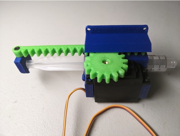
You could replace the rack & pinion of this STL file and simply attach a line to the servo motor's shaft.
But again, I don't know if a micro-servo will have enough rpm and torque for a 5 bar pressure at 1/5 of a second.
It is consistenly annoying and relieving it is to search for a myriad of different complex systems just to go back to the simplest idea one could have...
I went from a 1 ton lifting hoist mechanism back to artificial muscles just to go back to a hoist mechanism to pull a syringe...
I don't know how to feel about this...

Well, putting aside my feelings, I completly forgot to calculate the energy required to pump the fluid.
Although I said that the torque would depend on the piston diameter, it don't really matter when it comes to wattage.
If the syringe piston's head has 3 or 30cm of diameter and moves Xcm, it will need the same wattage to move 60ml of liquid, although the torque and speed of rotation would be different.
So, accordingly to the pipe volume calculator, if the inner diameter, and thus, the bore diameter was 2cm, I would need 19.1cm of length in order to fit 60ml.
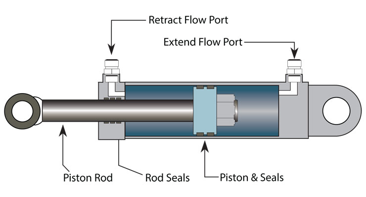
And thus, I would need to move 19.1cm in 1/5 of a second with a force of 16kg (accordingly to hydraulic cylinder calculator, 5 bar of pressure would apply more or less this force to the piston head).
Assuming that the diameter of the electric motor's shaft is 1cm, accordingly to the rpm to linear speed calculator, I would need 1800 RPM, and accordingly to the torque calculator, I would need 0.8 Nm of torque.
And finally, accordingly to the Torque to Horsepower Calculator, I would need 150 watts of power in order to pump 60 ml of fluid in 1/5 of a second with 16kg of force.
Assuming that I'm using the 25mm inner diameter pulling hydraulic cylinder with 2 bar of pressure, then I would need half of that wattage because it would need more or less 70ml. Needing 1.5 watts per kg of force.
Actually, no. I actually made the math and I would need 30 watts of power. 600 rpm to reach 30 cm/s and 0.4 newtons to apply 10kg of force with a shaft with 1cm of diameter. Resulting in 3 watts per kg.
However, like I said before: the muscles may need 20ml per filament instead of 6ml, so this value may increase 3.33 times.
And thus, it may use 4995 watts of power in order to fully actuate 10 muscles with 10kg of force each, totalling 49 watt per kg of force.
If I'm going to apply such wattage with dozens or hundreds of tiny electric motors to convert electricity to hydraulic force, better off just using electric motors by themselves.
... Which is good on paper, but not in reality.
I can DIY my way into making a single big electric motor, not hundreds of tiny electric motors.
By the way, I took a few minutes to calculate how much energy a system with a central pump would need.
Basically, assuming that each 25mm inner diameter hydraulic pulling cylinder uses 20 bar of pressure having a stroke of 15cm and are only 30 in total, I would need around 300-400 liters per minute of fluid flow, totalling at least 15-20 horsepower at 2500-3000 rpm, rotating 3 to 4 pumps in order to supply everything fast enough with enough force.
This would be around 100 watts per kilogram of force.
(this is me from the future, this math seems faulty, since each limb/muscle bundle would equally distribute the loads)
I really don't want to use a central pump/motor because of this, even the low efficiency of the electroosmotic pump would be better.
And again, I can't fit a single pump with a single motor for every actuator, it would simply be just too bulky and heavy (and costly).
I really need a way of circumventing such problem... But I don't have the money to try it...
Discussions
Become a Hackaday.io Member
Create an account to leave a comment. Already have an account? Log In.
You know how, many logs ago, you had the idea of stacking 50 electromagnets? What if, instead, it's 50 tethered blocks of iron and one long tube that is the same length as the blocks without spacing and coils around it like that solenoid pump idea. It could be possible to use "non conductive" / "single side conductive" copper foil to make the coils instead of enameled wire, potentially bringing benefits such as easier/more consistent DIY coil winding, improved heat dissipation and more copper packed into the same volume in comparison to higher current carrying wire.
Are you sure? yes | no
I think that is a good idea, but I'm not very confident on the copper foil as a coil.
There is a type of copper coil that uses something similar and it is called a "Bitter electromanget": https://en.wikipedia.org/wiki/Bitter_electromagnet
But it uses the copper-based foil in a paper wide coil.
Also, solenoids aren't known for being very efficient, nor light (a 5kg force solenoid weights almost 1kg of pure copper wire). Linear electromagnetic motors such as the one you suggested are often used for high precision and light applications.
However, I do think it is worth having a look given into it. I will try to search on the subject.
Thanks for the suggestion :)
Are you sure? yes | no
... But maybe it can work with the Lorentz force principle I talked about in the last project log.
Still, I can't test it yet because I'm too broke to even buy a power supply... :/
Are you sure? yes | no
I received an interesting answer:
"You don't need to roll it in a spiral, you can roll it in a cylinder, with one layer on top of another and it will make an inductor (thats how some transformers are built). Add a core, apply current and you have a solenoid.
Why you're concerned with long solenoid is confusing. The function of a solenoid is dependent on magnetic field strength, which is based on 4 factors: the number of turns/loops, current, core material and overall length. The first three are multiple and then divided by the fourth, so a longer coil will create a proportionally weaker magnetic field."
Are you sure? yes | no