It happens that I wrote so much on the first Project Log 74: Tech Tree for Mechs¹. that the hackaday Website started deleting older text. :|
I contacted the Hackaday email asking if it was possible to check older edits so I can copy the part that was deleted (I received an automatic email response saying they would take like a week to answer).
... And no, I don't write my project logs in a other documents. Yes, I'm that stupid.
... And that is why I completely lost whatever it was deleted. Forever. :|
-----------------------------------------------------------------------------------------------------------------------------------------------
I literally cannot write a single new phrase on the previous project log, but basically, I think it would be worth it making the electromagnetic artificial muscle I suggested making with the nanometer 3D printer with actually the airbrush 3D printer.
I know that it would take ages 3D printing and calibrating properly, but it would still be possible. I just don't know if it would be viable or practical, still, you would face the same problems relating to 3D printing electronics with resin and metal powder.
Well, I'm still not actually giving up on the mech idea, but I'm simply have a lot of difficulty find solutions (cheap and simple solutions) for the actuator problem.
Like I said in the previous project log: I settled on at least trying to find a way of making a solenoid pump or something that can be used as a pump and doesn't need electric motors, combustion engines nor piezoelectrics.
Electric motors are expensive and need really big batteries, combustion engines are low efficiency, expensive, heavy and need solenoid valves, piezoelectrics can't be homemade, aren't efficient and neither can pump massive volumes.
I mentioned the possibility of using Nitinol Shape Memory Alloys, but those have efficiencies below 20% and cost 500 dollars per kilogram.
By the way, while asking my trillion of random questions over and over again, ChatGPT said that the conversion of electricity into heat (using a heater like Nichrome or other types) is almost 99% efficient, and that the conversion of heat into steam using this method is almost 99% also (I searched online and it seems to check out).
So, there is also the option of using steam to pump the fluid or something else. You could use steam instead of pneumatics or hydraulics, you could use it to make a steam engines ( that are around 40% efficient) and so on (turbine engines sit around 65% to 90%). I also believe that steam powered artificial muscles would be as efficient as pneumatic ones (30% of efficiency or less) because they are essentially the same thing, but using different fluids.

Source: https://www.science.org/doi/10.1126/scirobotics.aaz4239
It is a unthetered artificial muscle in which induction heaters are used to heat iron oxide nano-particles in order to turn water into steam, making the muscle actuate. It is less efficient than what I'm suggesting.
But I don't know which is the best method, and to be honest, I don't feel comfortable carrying an electric steam boiler on something that can simply fall on the ground and break what is basically a bomb.
The few positives that I can think of would be the speed of actuation, compared to hydraulics and electric motors, it is hard something as fast as a pneumatic actuator consuming the same amount of energy.
Not to mention that you wouldn't need the power of a turbine engine to compress thousands of liters of air.
... But it is also not that simple.
I would need to calculate how many liters of water you would need for a given pressure and flow of steam, which, as far as I could calculate in the past, it ins't that hard, but it isn't that easy either. It would entirely depend on the full system.
1 liter of water produces 1600 liters of steam.
Maybe it could be useful for an ornithopter...
But going back to the real subject:
Steam powered artificial muscles:
The same problem of pneumatic and thermal artificial muscles arise: which is how to control its actuation properly.
I found a few suggestions that have its own pros and cons:
- Completely activate single strands based on how much weight you want to lift and how far you want to lift.
This one I accidentaly found out about when looking for Battlemech, ironically.
The description is that these are high voltage activated electric artificial muscles that activate independent strands.
 However, as you can guess, I can't possibly do that because each individual capillary-thin strand would need its own independent valve, and each independent valve would need to be controlled.
Buuut this idea could really be useful for thermally activated artificial muscles, like the Shape Memory Alloys and that carbon-fiber-silicon rubber one I showed on the previous project log.
Another idea for thermal actuators is divide the actuators in sections, so you could progressively contract certain parts of the artificial muscle fiber. But it would be a pain in the ass to wire everything.
I also gave the idea of simply spraying cold water at the rate parallel to the thermal muscle contraction in order to make it contract in a certain distance.
But how to control the force?
- Another option would be to "simply" turn the appropriated amount of water into steam required for a given action.
... Which is really not that simple. And just like I calculated in other previous project logs, the faster you want to turn water into steam, the more power you would need. To the point a single small muscle would require 2000 watts of power to contract in half a second.
However, a possible way of combating this would be to have multiple independent and interconnected steam generators throughout the body of the mechsuit/exosuit.
This way if one steam generator is not enough to supply a given action, others will open their own valves and help with the extra boost.
But, as you can guess, this option still requires a lot of solenoid valves and careful control, which means proper programming, which is not my forte.
And yet, I like the idea of multiple small steam generators instead of a single big one. If one of these were to blow up, the detonation would be smaller and less dangerous.
- Another obvious option would be to copy the already existing pneumatic controls, but use it for steam.
Normally, if an actuator (like an arm with pneumatic artificial muscles) wants to make a precise movement, opposing actuators would be opening and closing in order to reach that position. A biceps can't move if the triceps is already pulling it back, which would lock the arm in the desired place.
This need a fine, precise and very expensive kind of sensors, progressive valves and it is really inefficient since half the effort of the arm will be spent counter acting the arm.
This option is not very good in my opinion.
- There is still the simpler option of simply making steam with the electric method and rotating a steam turbine that would rotate an hydraulic pump.
But, as you can guess, this method wouldn't be so simple. And steam turbines are heavy and expensive.
However, they seem to be very versatile, since this one here (accordingly to the random website I found) could output a power between 100 to 3000 kilowatts of power (which is absolutely insane).![]()
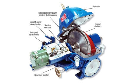
By the way, the bigger the steam turbine, the more efficient it is and the slower it needs to spin (just like helicopter/turbofan blades), so, depending on the amount of horsepower/watts I would require for the Mechsuit/Exosuit, I would need a custombuilt steam turbine engine.
But even then, if such an insane idea of using a steam turbine engine on the backpack of a Mechsuit/Exosuit works out somehow, you would still find the issues regarding common hydraulic systems: solenoid valves, control feedback and so on.
- The ideal manner of pumping water using steam would be using steam itself without any mechanical means.
The best two results I got were Vacuum Ejectors, buuut I don't know how to make it to pump water and refill the steam boiler at same time using a Steam Injector.
In normal occasions you would either use one or the another.

The vacuum ejector uses a higher pressure fluid to create a vacuum and mix with another fluid in order to create a very efficient mixer or a high airflow thingie.
I couldn't find anywhere the efficiency of steam ejector/vacuum pumps.
I found a source that claims it to be 90%, but ChatGPT/BingGPT says it has around 10-40%.
I asked an engineer in a discord group and he said that the efficiency depends on the type of fluid being worked. air on air = 90%, air on liquid = 60%, liquid on liquid = 30%, but in the source I talked, the pressure being ejected is at 1.1 bar since this is a mixer, not a pump, meaning that proper pumping has to be properly tested.
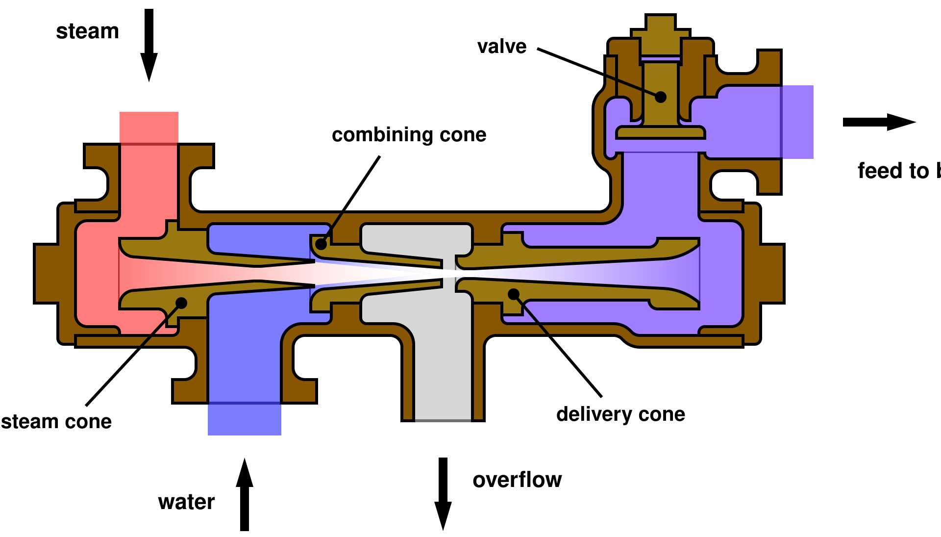
A steam injector on another hand, uses the higher pressure steam from the boiler to pump water back into the boiler.
Since this would be a new type of pump, I can't tell how efficient such pump would be...
- I did found out about pistonless pumps, which operate in a different principle and are quite interesting as far as I could see.
Of course, just like any other steam mechanism, it is way more complex when you want it to do something you want...
Savery Pistonless pumps are simple: fill in a tank with steam directly connected to water, the steam will expand and push the water, then you let the steam get cold and create a vacuum, pulling the water. Rinse and repeat.

They even used a similar approach for a rocket engine in order to save weight and money instead of using turbopumps.

Source: https://arc.aiaa.org/doi/10.2514/6.2014-3784
For last, there is the Pulsometer pump that also works with the same principle as the others, but with a different structure.

If I'm not understanding this incorrectly: it works the same way as the others, but it has extra chambers, allowing for a continuous operation unlike the Savery's one, which needs to wait the steam to cool down.
Well, if these are the equivalent to a piston pump, I wonder what would be the equivalent to a centrifugal pump...
... But the problem comes back to the efficiency problem: expanding steam is just like pneumatics... And pneumatics aren't efficient.
A piston steam engine has 40% efficiency, and this is basically a piston steam engine, but without the pistons... So... It is safe to assume comparable efficiencies.
Well, I forgot to talk about Dielectric Elastomer Actuators.
The video explains it very well, but basically, the non-conductive elastic medium is sandwiched between two conductive layers/electrodes, once static electricity is passed through it, the two layers attract each other, simulating a contraction.
The funny thing is that this is actually a shape-changing capacitor.
Capacitors have three layers: two electrodes and a dielectric (non-conductive) layer.
A bunch of electrons are concentrated on the electrodes and since they have a dielectric (non-conductive) space between then, it keeps them in place by the electromagnetic attraction, once the two sides are connected, the electrons instantly jump all at once to the other side.
(By the way, for the little I think I know, there aren't positively charged electrons? The only thing that can be called "positively charged" is something lacking electrons, no? I'm confuser)
In anyway, I just didn't give much credit to this type of actuator simply because I don't know what is their efficiency and how precisely are these made.
Some articles say Dielectric Elastomers have more than 80% of efficiency, in others it is said they have less than 20% of efficiency.
They normally have a really, really small stroke, less than 10%.
On top of that, there are numerous and numerous types of Dielectric Elastomers.
Some are based on acrylates, some are based on silicon rubber or are fluid assisted, some use carbon nanotube electrodes, others simply uses graphite powder on its place.
And I can't find enough information properly comparing each type's performance and efficiency, the information is all over the place, scarce and imprecise.
I would need to build every single type and personaly test every single one, but some need such complex polymers that I would need to directly contact some chemical factories for custom orders on the materials.
Example:
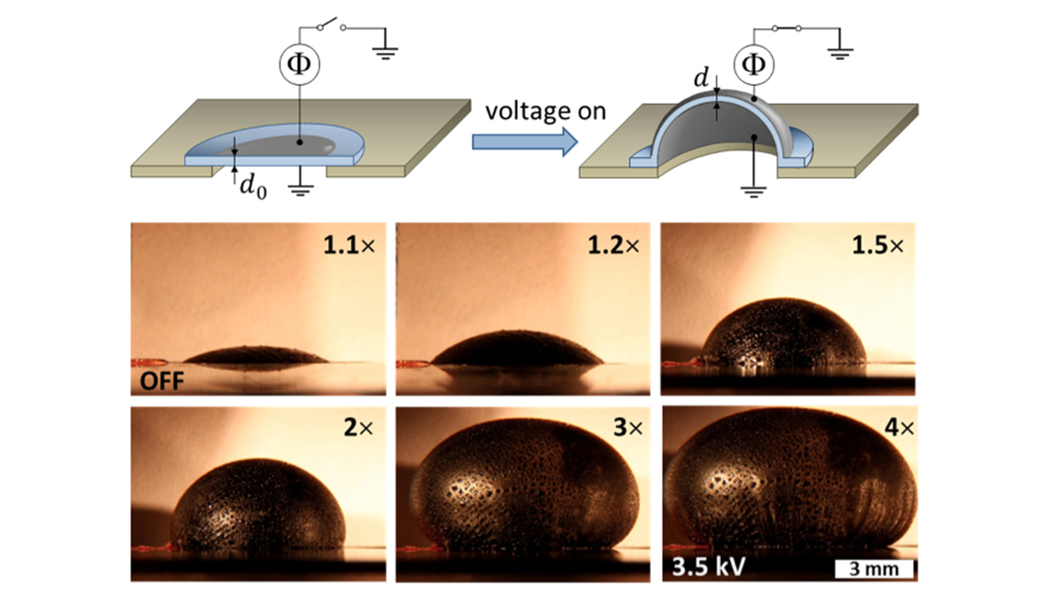
This dielectric elastomer is a modified silicon rubber to be used specifically for this porpuse, it can have a stroke of 300%.
I couldn't find what the hell is a "bottlebrush polymer", but after searching a little bit on google, I think I found something that is probably the same thing, which is a normal silicon rubber being modified by at least 3 compounds:
- PDMS Monomer: Monomethacryloxypropyl terminated polydimethylsiloxane.
- Crosslinker: Methacryloxypropyl terminated polydimethylsiloxane.
- Initiator: hermal-initiator: 2,2′-Azobis(2-methylpropionitrile).
To me, these three sound like old eldritch god forbidden names.
Not to mention the myriad ways you could stack these dielectric elastomers for different porpuses.


Also, as you can see, the dielectric elastomers are a reversedely actuated artificial muscles, meaning that they relax when activated and contract when disactivated.
After all, the two electrodes are attracted when charged, not the opposite.
Of course, it depends on the type of stack.
In any manner, I am divided between the vertically stacked and the spiralled/cylindrically stacked, simply because I could add milk-graphene to the flexible electrodes and absurdly increase the strength of the silicone rubber, while that is not an option for the vertically stacked...
(I think this is a good way of making the cylindrically stacked dielectric elastomer:you restrain one of the parts and it curves, it would curve in one direction, this one shows a different set of fibers that work like Mckibben which would coil on itself [supposedly]).
The spirally stacked would have its electrodes connected end to end while the vertically stacked would be divided with soft silicone in between...
Assuming that I wouldn't do the same thing as the electromagnet idea where the conductive connecting parts would be on the outside.
On another note, I could see the Spiralled stacked being easily mass produced, you would only need a conveyor belt and three airbrushers making three continuous layers of dieletric elastomer that would be solid by the end of the belt, which would be automatically spiralled and twisted, just like a rope.

But I don't know how the vertically stacked could be mass produced, I can imagine it being 3D printed with specialized conveyor 3D printers, but not as fast as in the gif.

However, I do think that this has the same problem as the stacked electromagnetic artificial muscles that I suggested previously: stacking the dielectric elastomers won't stack their strength, forcing you to make multiple parallel strands to increase strength.
Which is impossible to do by hand, forcing you to use a 3D printer specific for this job.
On top of that, using airbrushers would severly add air bubbles to actuators, forcing you to use a vacuum chamber to get rid of them.
... Which wouldn't be possible with a mass produced process of airbrushers, requiring conventional 3D printers:
(this is me from the future, you could mix silicone rubber with alcohol or put it on a warm surface to get rid of the bubbles, but syringe 3D printing is also nice)
... But this also brings up other problems: like in the thumbnail, the actuators would be too thick.
The thinner the layers are, the better the DEA works. Some papers used electro spun layers of silicon and electrodes, the same method used for microchips and other things.
Of course, one would need to check how much the air bubbles would interfere with the performance of the DEAs and how much the thickness would also interfere in order to find a middle-ground or a better option of the two.
... Which would need to be tested...
(ChatGPT and BingGPT said that thickness messes up with the response and softness, air bubbles with the capacitance and life cycle)
By the way, you could use any kind of conductive material as long it has the two flexible electrodes and a flexible dielectric filler.
This means that you could even use polymers, normal rubbers and so on.
And as such, maybe you could get rid of the air bubbles using plastics like PVA and/or PVP...
By the way, dielectric elastomers use electrostatic current, meaning that the voltage is on the 5 kilovolts, but with an absurdely small amperage.
So, 5000 volts x 0,0001 amps = 5 watts, Just like 5 volts x 1 amp = 5 watts.
The conversion of normal current into electrostatic has also its own inneficiencies.
Even so, it has its own limits (as shown in the first video on the subject), you would need to find the ideal thickness and the ideal way of carry the electric charges through the actuators.
The same problems I talked about the electromagnetic artificial muscles, which the same (possible) benefits of being simple and as fast as electricity can be.
I looked in a random wire diameter calculator and for a 5000 volt and 0.001 amperage, I would only need a AWG 25 copper cable, which has 0.4 mm of diameter, even if you had 100,000 meters of cable.
And as thus, it is probably not a big deal to calculate which should be the thickness of each part. An advantage over the conventional electromagnetic artificial muscle.
After all, I still couldn't find a way of calculate what should be the thickness of each wire based on is resistivity.
I tried asking to ChatGPT and BingGPT multiple times, and accordingly to them, I would need a cable with 1 cm to 10 cm of diameter to transmit a 1 volt 8 amp current through a material with 5.56e-7 ohms per meter of resistivity (the resistivity of electrolytic copper powder). While electrostatic current in the other hand, would still need the same diameter of the previous calculation (0.4mm to 0.2mm) to transmit the same amount of watts.
Guess Dielectric Elastomers seem to be the winner... 🤔
... If it wasn't for the fact that I can't possibly figure out its efficiency, stroke length and strength.
(Doesn't that mean that I could simply change the actuator for an electrostatic electromagnet instead of a dielectric elastomer?)

Source: https://www.science.org/doi/10.1126/sciadv.abc0251

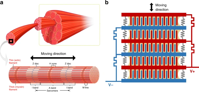
By the way, comb drives use a system similar to biological muscles, but they use electrostatics in order to work.
However, these are used for sensing. One could make them this same way, and these aren't insulated, one could maybe add something dielectric or non-conductive layer to avoid short-circuiting between the teeth.
Although I don't know which would be best...
ChatGPT said that an insulator layer wouldn't work.
"In electromagnetism, a dielectric (or dielectric medium) is an electrical insulator that can be polarised by an applied electric field." Wikipedia.
(why did I've made an habit of checking wikipedia as the last resource? Bruh
I'm suggesting this other type of dielectric/electrostatic actuator because to me, it seems easier to 3D print and mass produce, since it wouldn't have the same issues as the other types I talked about before;
The dielectric layer don't need to be soft, in fact, almost no part on it needs to be soft...
But it would still benefit a whole lot if it was as thin as possible, however, since the elastomer is so dense, I think it would compensate for the lack of thinness?
I found this document: https://escholarship.org/content/qt7kf261zf/qt7kf261zf_noSplash_e480d01e957c9dd7a9e06b13b7356899.pdf
In page 38 it has a chart with different types of dielectric elastomers, and their efficiencies vary between 80% to 90% and a strain/stroke of around 30% to 60% (with the exception of pre-strained acrylic, which achieves 300%).
If it is so simple, then why companies aren't employing dielectric elastomer actuators in their bipedal robots and whatsoever?
What I'm missing...?
I asked on Quora and other websites including ChatGPT and BingGPT about this and it seems like the "catch" is the durability of this type of actuator.
Some sources say these only survive 1000 cycles, others say 1 million cycles.
I searched the amount of cycles that humans take for every hour, and it goes around 4800 to 13000 cycles per hour, which would mean each dielectric elastomer actuator would survive for only 3 to 8 days of non-stop walking (if its durability is around 1 million cycles).
On the dielectric elastomer wikipedia section itself is said that using hydrogels is a possible way of increasing its durability.
ChatGPT suggested me making an hydrogel using PVA, borax, glycerol and a conductive powder like salt, with the exception of the later two, this is basically the recipe for shear thickening fluid, lol.
By the way, I was thinking of using hydrogels for the electrodes and silicone rubber for the dielectric part that is to be sandwiched.
Not to mention the low strength, but that could be solved by simply twisting the filaments just like they did with fishing line artificial muscles, which have even lower stroke lengths and even lower force values.
... One thing makes me wondering, though... If thee actuators work like capacitors, wouldn't that mean that the actuators themselves are capable of storing energy somehow? And that energy could be reused for other actuations? Increasing its overall efficiency...?
By the way, dielectric elastomers are both sensors and actuators, so you could also make them into a sensor/haptic feedback system.
If you figure out a way of making a dielectric elastomer actuator that can withstand the strengths in a mechsui/exosuit, maybe you could make ornithopters...
Oh yeah, I almost forgot: you can still choose to use the dielectric elastomers as hydraulic pumps instead of use them as the primary actuator.
By god I hope this is the last time that I edit this project log (today is 31/12/2023, I've created the first tech tree log 2 months ago)
Well, let's just remember that I'm going through all this trouble of studying every single type of artificial muscle because I don't know how to make Carbon Nanotube artificial muscles.
I heard they are extremely efficient (I couldn't find any kind of precise information for that), but as far as I could find, the electrical way they activate is through Lorentz Force, which is not that strong, neither that efficient. But the carbon nanotubes have advantages over other mediums (such as copper wires) because they are on the nano-meter scale, and thus, the closer the electromagnetic field, the stronger it is.
This is the video in which he explains how the muscle works, which sounds extremely similar to how lorentz force works. One could still use extremely thin copper wires or other materials for that.
The thinnest copper cable is AWG 50, which has 0.02 mm of diameter, which is 20,000 times bigger than a medium-sized carbon nanotube (just now I found out about copper nanowires and zinc-oxide nanowires, but I couldn't find any source explaining how to make them in a way as useful as carbon nanotubes, they are normally used as conductive powder/catalyst).
On top of it, the last big breakthrough on the production of carbon nanotubes was 3 years ago and it was growing 12cm of it uninterrupted for days, and to me, it seems like it would need some post-processing.
You literally need to pump acetylene gas (explosive, flamable and unstable) in a chamber with a metal plate at hundreds of degree celsius.
How you do that in a homemade setup? You don't.
And there really isn't any other way I know of, because if it was, carbon nanotube muscles would be common.
You know what I said about metal oxide nanowires? There are also polymer based nanowires.
There is a crapton of ways of making these polymer based nanowires out of conductive polymers like Polyacetylene, Polyaniline, Polypyrrole and Polythiophene (I can't find them to buy online, only through polymer factories).
But while searching I think I got an idea:
There are syringes which have needles with an inner-diameter in the 2-5 nanometers of opening, these are called nanoneedles and are super cheap to find. From tattoo pens, to syringes to insulin pens.

This means that I could simply mix conductive polymers and conductive materials (like graphite or copper nanopowder) and extrude them through these nanoneedles, making little spagethi streams of conductive nanowires that are the same size as caron nanotubes and would act just like them (maybe). :|
I don't know how well it would work, but you could dissolve conductive polymers on acetone/glycol/ethanol and extrude it on warm (warm, not boiling) oil, so the polymer can dry out and not be on risk of simply breaking due to its absurd thinness.
(But since I can't find conductive polymers for the life of me, I would either make super fine graphite/graphene powder or try to make a graphite mold out of the needles and extrude molten copper)
... I kinda feel stupid since I didn't had this obvious idea before.
But to be honest, it is hard to tell if adding conductive powder will work, after all it is a needle with around 2-5 nanometer of diameter.
What garantee I have that the powder won't clog and probably damage (or even pop) the syringe needles?
I would be forced to either make a super ultra mega DIY thin powder or I would need to use only conductive liquids/polymers in order to make it to work.
maybe I could also use the same techniques used on carbon nanotubes in order to increase its strength, stroke and efficiency.
... Actually, the more I think about this, the less it feels like it wold work. The carbon nanotube artificial muscles uses voltage charges, meaning it is dielectric.
I could simply make graphene infused silicone rubber nanofibers with PVA/teflon as an "enamel" layer, but even then, I don't think it would work...
By the way, this nanoneedle also means that I could make super ultra thin dielectric elastomers (if the nanowires doesn't work out) with PVA on the electrodes and pure silicone rubber as the dielectric material (or the reverse).
I wish I could add the extra thingies that I talked about (graphite/graphene powder), but it wouldn't pass through the nanoneedles.
Speaking of which, would a fibrous electrode dielectric elastomer work?
What I mean is: nano-wires A is the entire positive electrode and it is covered in dielectric material (like enameled copper), nano-wires B are the negative electrode and they are exposed (or also covered), would these two fibers attractand coil on each other? Like a muscle?
However, if you change what you want from the muscles, the picture changes a lot.
Specially if you want a high lifting to weight ratio.
I were only looking at the speed, strength and easiness of production, but if you look at the lifting ratio, all of them are quite bad.
The dielectric elastomer silicone rubber can only achieve a lifting ratio of 10 times its own weight (10:1), meaning that if I wanted to lift 3000 kilograms, I would need 300 kilograms worth of dielectric elastomers. Even the elastomer muscle video can only lift 50:1. The steam muscle is a really good option, but I'm really afraid of the consequences of using high pressure steam. The nylon/polyethylene only achieve 100:1, the hydraulic and pneumatic ones 1000:1.
(By the way, just now I remembered that the dielectric elastomer has a limited lift-to-weight ratio because it isn't various fibers, the same problem with the electromagnets stacked one above another)
But the winner of them all (in force to weight ratio) is the thermal carbon-fiber/silicone rubber artificial muscle, which can lift 12,000 times its own weight.
This muscle and this muscle works by the expansion of material, pully the fibers apart, just like any mckibben muscle, the difference is that the material is solid and the fibers are inside of it.
Yes, I would need to add a whole amount of sections to heat it up progressively like I talked above, plus the water spray for instant cooling, but it would still be more practical than the others.
However, I was wondering if adding polyethylene/nylon would make the muscle work better, since it depends on the swelling of the silicone rubber heated by the carbon fiber.
Accodingly to ChatGPT and BingGPT, silicone rubber has a high coefficient of thermal expansion, unlike polyethylene and nylon, which have half to less of it.
Well, if that is so, I wish I knew more about the properties of materials in order to seek out the best ones for artificial muscles. If thermal expansion coefficient is better at certain materials, then the thermal coefficient of others won't be as attractive. I can only imagine if I knew what were the best properties of every material in order to make the perfect artificial muscle...
I thinkit would be like searching for a good orange for a bitter plate and knowing that a lemon is a better source of bitterness.
By the way, silicone rubber has a coefficient of thermal expansion (CTE) of 200 to 400 ppm/ºC.
- Ethylene-vinyl-acetate (EVA) with 950 - 960 ppm/ºC
- Natural rubber with 920 - 930 ppm/ºC
- Polychloroprene (Neoprene) with 1,200 - 1,300 ppm/ºC
- Polyisoprene rubber with 930 - 940 ppm/ºC
- Polyurethane with 1,000 - 1,300 ppm/ºC
- Silicone elastomers with 1,300 - 1,800 ppm/ºC
These are the materials that BingGPT sent me.
By the way, I saw this thermal artificial muscle made out of HDPE and COCe (Cyclic Olefin Copolymer Elastomer). I can't find COCe to buy online for the life of me, but maybe with the use of EVA, Polyurethane and meltable rubber, one could replace it with a more common material.
Being honest, after all this useless talk, I really don't know which option is best... I just feel stupid and useless to be honest...
Third: Structure.
The actuators need an skeleton to be attached to.
This one is not an actual impossibility at the moment, any kind of aluminium, steel or even plastic can support the force of the muscles and the weight of the mech.
The problem is that you would need to design the damn structure and go through the problem of actually building it, which would be both labor intensive and require a professional engineer to check/project such structure.
I thought on maybe trying to make a 3D model on my own using FreeCAD or Blender, but sincerily, I don't think I have any will power left in myself after 1 year of hitting roadblock after roadblock with this project.
What would even be the point of giving my all on making an articial skeleton since all other problems weren't solved?
I don't even have the money to test each part of the project, imagine actually building it.
Relevant to remember Hacksmith industries, they've made actual mechs (including the one above), and in all videos they show how difficult such task actually is.
I mean, they are sponsored professionals, so they have all the resources and all the resources that they needed.
... And yet, they had a crapton of difficulties, almost gave up on the project and still, on the end, the robot simply broke up, ending their years of effort.
Now, imagine me, a dumbass without any kind of degree on anything useful (I have on graphic design coff coff). Trying to do a mech. Alone.
In either way, one would need to plan how many tons of weight each limb would support, and on top of that, figure out if the structure will handle falling into the ground, running, jumping and whatever other actions one would need to peform.
Let's just remember that each part of the body is technically a lever, and each subsequent part of the body needs to be more powerful than the previous one. The shoulders would need to be X times stronger than the arms, the torso be X times stronger than the previous two and finally the legs that would need to be X times stronger than all others.
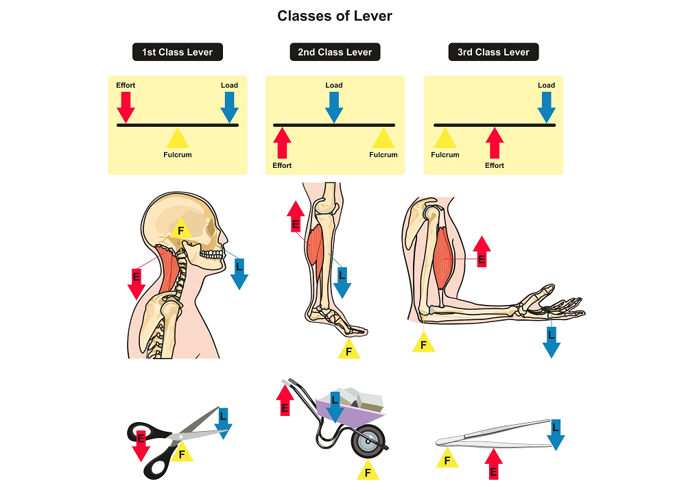
The "best" rule of thumb is to make everything somewhat stronger than it needs to be and make the legs 3 times stronger (it is said that the lower part of the human body is 3 times stronger than the upper part, and that is why you can carry weight and still be able to run and jump, besides your own weight).
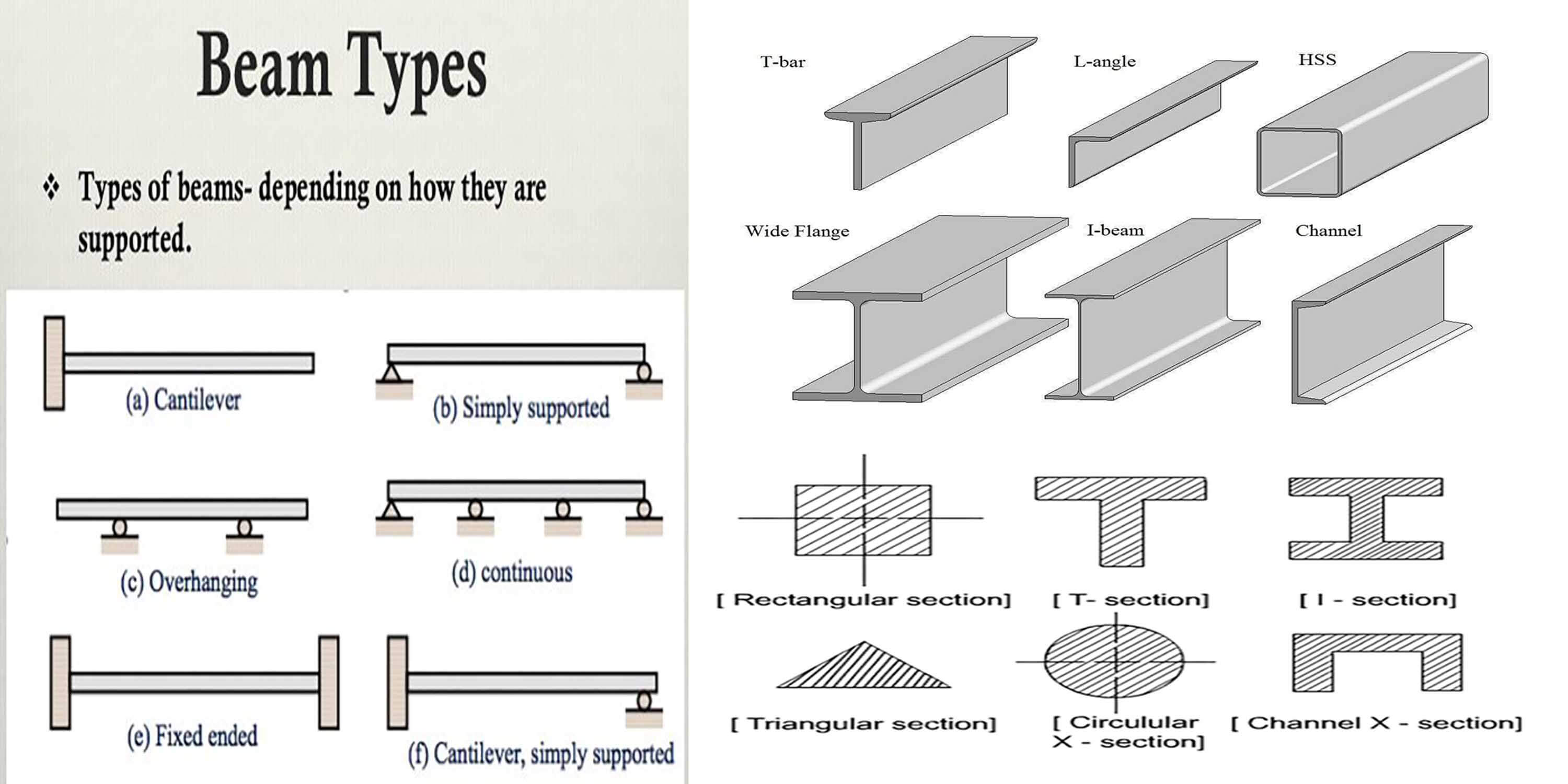
I thought on using High Density Polyethylene (HDPE) reinforced with fibers (of whatever type, glass fibers, carbon fibers, even wood fibers etc) at first because I could simply recycle it, but I couldn't figure out how thicker the structure would need to be. And assuming that the tensile strength of HDPE (around 20 to 30 MPa or 300 bars) is 1:1 to kilograms, then it would be able to sustain 300kg... But I don't know at which thickness, which structural shape would be the best and so on.
The same applies to Aluminium, which I thought on turning it into heat treated aluminium 6061 or aluminium 7075 and on top of that, reinforce it with iron or steel cables, like a metal composite.
But aluminium is terrible with fatigue, in the sense of being not that good with dealing with repeated tension/compression cycles very fast, like in a mechanical component.
Drag cars use aluminium piston rods on its construction because of the light weight, but these same piston rods wouldn't last more than a month in a conventional car.
However, I don't fully understand metallurgy and how much material properly acts under certain circumstances. Which a professional would be able to tell.
I also thought on DIYing Titanium Aluminate, which is a 60% Titanium 40% aluminium alloy that uses the benefits of both alloys.
I would be doing that by taking titanium dioxide (which is both a food and agriculture product that is really cheap) and use the hydrogen reduction reaction to take off the oxygen from the titanium.
But even then, I would need a furnace that reaches the temperature of titanium to melt (2500 ºC) which is not easy even with industrial standards.
Steel is the final option, and I thought on mixing silicon and tungsten with it in order to create a good steel alloy like AR 500 or other types.
But Steel is hard to deal aswell, and the tools required to weld, forge, hammer and cut are expensive and equally as heavy.
One would need to actually figure out how much material and in which shape, size and weight each type of material would require to be in order to make something appropriate for a mech or/and an exoskeleton.
Fourth: Control.
Well, what is the need for a mech/exoskeleton if you can't control it?
Like I said in the beginning of this tech tree thingie: you could "easily" overcome the problem of control and precision with proper encoders and programming, but you would exponentially increase the cost and complexity of the system. Just like an industrial robot, and those robots are as expensive (or more) than a house.
The best I could think/find was something similar to what James Bruton first did do his DIY Iron Man exosuit:
In resume, he put hall sensors (cheap proximity sensors that only know the distance it is from a magnet) in a rubber box, so the more he approached one of the points, the more the suit moved in said direction.
The idea would do the same thing to the Exoskeleton or Mechanoid suit, but putting the hall sensors in the body of the pilot on the same points the artificial muscles would be in the artificial skeleton.
So, if you lifted a biceps in a certain way, both hall sensors (under and over your forearm) would notice a difference in distance over time and try to keep the suit from overpulling and underpushing the arm as fast as it could; In the case of the exoskeleton it would be "easier" to do this, since the body would be moving with the suit at the same time.
The Mechanoid suit wouldn't be so easy, as far as I could think.
For example, if you made a solid shell around the pilot's body using this technique for motion control, the system would be more or less "blind", because you wouldn't be receiving the sensation feedback.
You would need some haptic system (a system that simulates the touch of the mech into your own body), it would be easier to do if you connected servos in some kind of motion suit like in the Avatar movie.
But I think it would be a little complicated to do that with an artificial muscle system.
Another option that I was able to think was to make a "second skin" both for the mech and for the pilot while connecting these.
Let's say, like a large blanket full of sensors (like piezoelectric sensors).
Piezoeletric buzzers/actuators/sensors generate a small eletric current when exposed to vibration and/or impacts, and when receiving electric currents can produce sound and/or vibrate in a certain way.
The problem is that this option would be pretty labour intensive and could be full of defects and problems, you could make a different "sleeve-skin" for every part of the body, but still, it would be a lot of piezoelectric buzzers.
Plus, how you would define the vibration?
For example, how do you know where is your mouth is when eating? You know that because your sense of touch is "on" all the time, this way you know where each part of your body is at all times.
How the vibration of the second skin would transmit the sense of touch all the time? What about scratches? Bumps? Impacts? Changes in temperature? How you would convey the information you want to transmit into the haptic suit?
By the way, there is a myriad of different ways of making haptic sensors, this one uses fluids connected to sensors (I forgot which type) and can be made with silicon, rubber or whatever other flexible material.


The problem is still the same: even if the "skin" itself is relatively easy to make and on the cheap, it is labour intensive.
Even if you could simply connect a flexible silicon skin from the mech to the person inside without any kind of electronics, how the heck you would fill and connect all the thousands of tubes? What if some of them rip apart or simply pops?
I also found this interesting article:
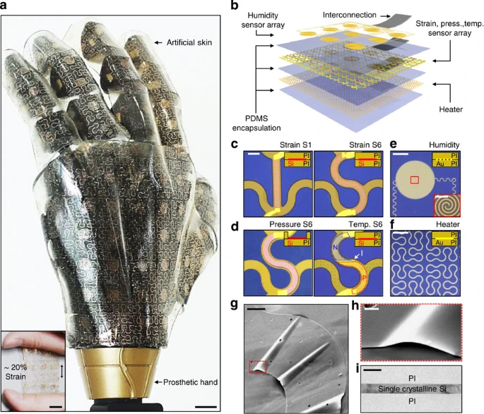
Source: https://www.nature.com/articles/ncomms6747
Well, I didn't read this article yet to see how they were able to make the sensors, but I would make a guess that one would be able to make printable skin sensors with conductive inks.
In each video below it shous varios methods for printing circuits and other types of sensors, including thermal sensors and even antennas.
(by the way, these printed circuits and sensors can be applied to any medium: paper, cloths, plastics, rubber sheets etc)
Well, I don't know what would be the best method of DIYing these printable sensors (using conventional printers or relief prints, like old journals were made), but one would need to figure out what sensor to put where and how to connect each one.
For example, what is the sequence of sensor layers you would need to use? Touch, thermal and humidity one above another? Maybe put each one on the same layer? How you would connect and transfer these sensations to the haptic suit of the pilot?
Would the printed sensors be able to be used as printed actuators?
While searching for a little bit, I found this electromagnetic ink printed actuator:
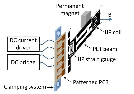
Source: https://www.mdpi.com/2076-0825/5/3/21
Well, it is not that useful for an artificial muscle, but maybe if you made a coil on both ends, it could be used as a vibration actuator for haptic sensing...
Although I don't know how I would make it through a large blanket/sheet, maybe you would need to align two sets of blankets that would attract and repel each other in order to make a vibration.
... But I don't know how perceptible it would be, a lot of things that I suggest would need to be throughly tested in order to be considered viable for its function.
... Which further increases the cost and complexity of the project.
I also found out this video this guy made, again, you could replace the magnet with an opposite magnetic coil.
The problem is that you would need to find a way of making a flexure stand.
Well, this madlad here made a speaker with conductive ink and paper:

Source: https://www.zachrotholz.com/paper-speakers.html
As far as I understand, sound is vibration, so if you can make a speaker with conductive ink and a mirroed coil (assume that the paper in the picture is folded in the middle), you've made a vibration actuator.
Maybe a good way of making a inkjet printed haptic actuator would be to not use any actuator at all, but electricity itself.
The idea would be to directly electroctute the skin with a small voltage in a sequence simulating vibration.

Source: https://www.nature.com/articles/s42256-022-00543-y
I found this article that uses hydrogel.
The only problem is that the haptic material needs to be in direct contact with the user's skin, which is not convenient if you want to wear clothes. >.>
Maybe this could be reserved for the feet, lower legs, forearms and hands. Which are exactly the parts of the body that you would be using the most, and you can easily lift you clothes for these parts.
I also saw other options that suggested using printed heaters for the haptic feedback, but I don't know how fast it would be to generate enough heat to simulate touch.
Also, I found this option here that I thought it was interesting:
01/01/2024 and I'm still editing this blasted project log.
Well, even though I said I gave up on the project, I still actively search on all my free-time simply because it is some kind of hobby, I suppose.
And one of those times while I was researching, I accidentaly found out about brain-computer interface.
The thing is that one could make a radar array around the human brain and interpret the sinapses/signals of the brain, spine or local nerves in the body in order to control prosthestics.
I couldn't find much information on the subject, and the little that I found, I didn't even gave a chance on trying reading them.
But let's imagine it like this: imagine the brain activity detection array of said radar is made of thousands of voxels with 1x1 mm of diameter.
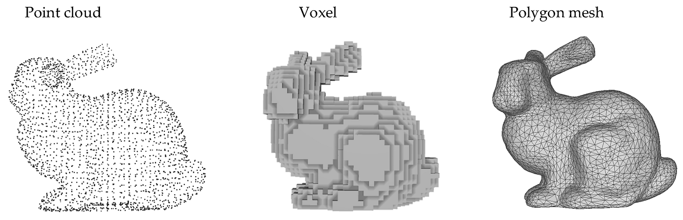
One could "brute-force" the interface by detecting the position of every part of the body, every part of the brain and making a Deep Learning AI to interpret the signals in order to command the prosthetics in a certain way.
This way you could control the mech/exosuit with your brain instinctively, maybe you could even help prosthetic users with such thing.
... The problem is: how to make said radar array? Can radars even be used to see human brains?
Magnetic Ressonance Imaging? This thing uses superconductors cooled by liquid helium and costs million of dollars.
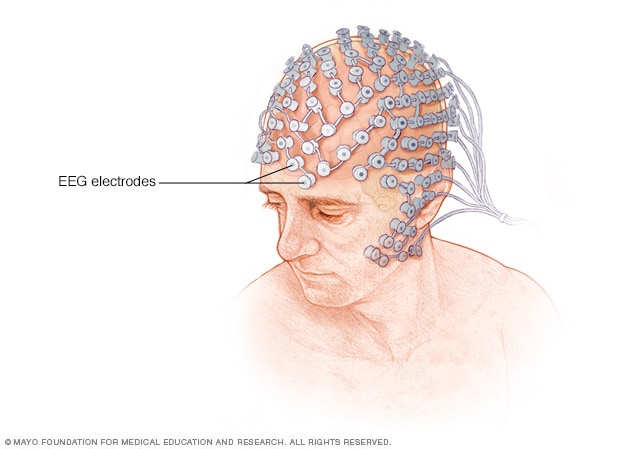
Electroencephalography (EEG) Sensors? These only work with a general activity of your brain.
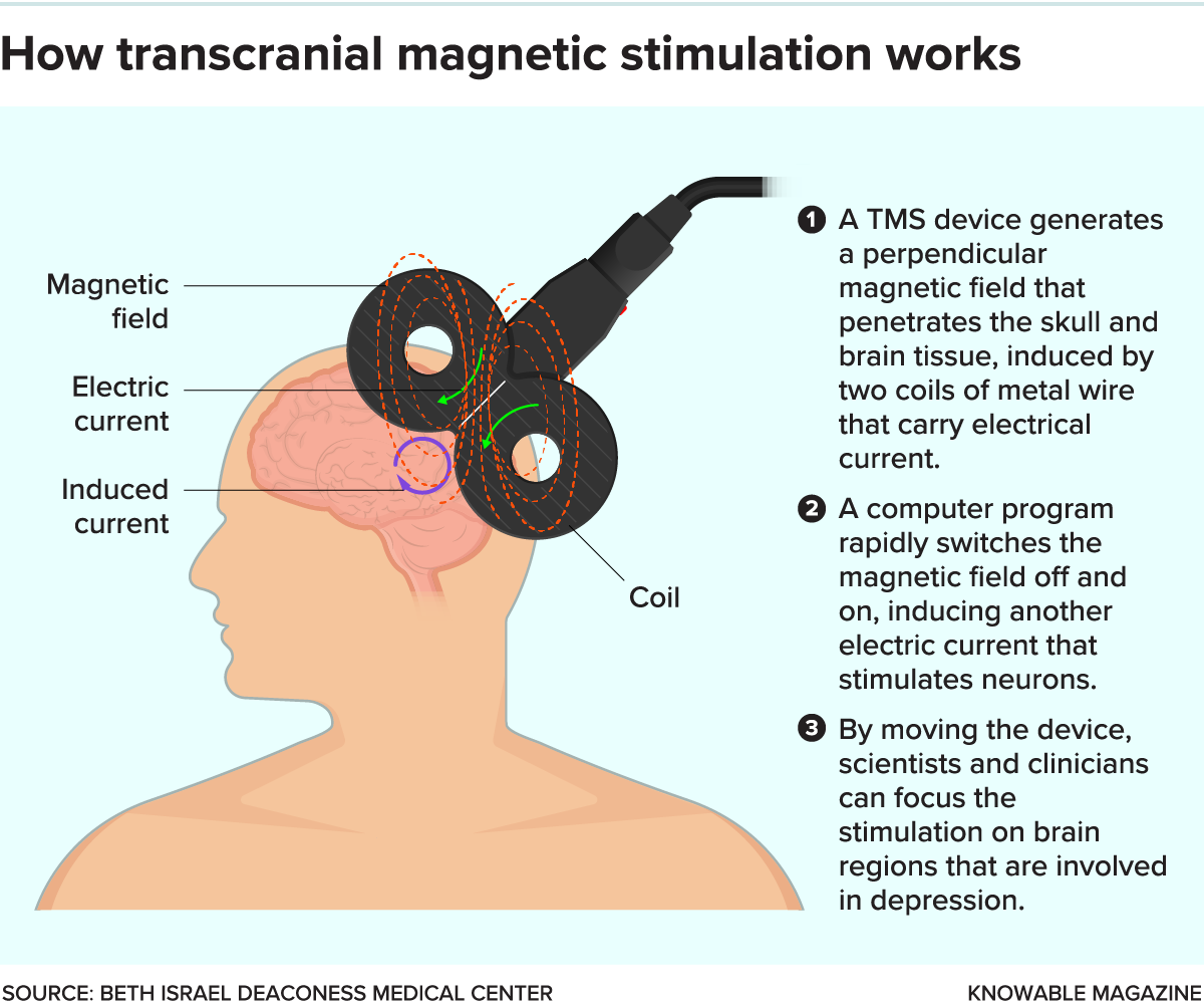
The closest thing I could find was TMS (transcranial magnetic stimulation), which works with induction coils (I think), which could be used both to detect and to induct responses on the brain.
Buuuut... As you can imagine, there isn't any kind of machine like that.
In fact, I don't even know if the MRI machines have such insane resolution as 1mm voxels, imagine doing it in real time while you think on a myriad of different things?
Imagine the amount of gigabytes you would produce per second.
With radars? What kind of radar can see the human brain? I just found this one picture, but it doesn't look like it would have 1x1 mm definition...
 Source: https://www.researchgate.net/publication/320360706_Radar_based_technology_for_non-contact_monitoring_of_accumulation_of_blood_in_the_head_A_numerical_study
(The induction coils make me wonder: could one use them to make a blind person see again by inducing currents on the eye nerves and/or on the brain?)
Accordingly to this link there are 684,000 neurons in a 1x1mm voxel.
... Which puts into question if this is enough.
Also, I don't have any idea of how to make a Voxel Scanner, but it seems like it is conventional practice on MRIs and the like.
The best idea I could come up with was simply imagining the electromagnetic waves as light, just imagine that each radar is a magnifying glass, focusing light in a single point in the air, and there are thousands other radars focusing on other 1mm focused light balls through your brain.
The obvious problem is how to do that.
The human brain typically has motherfricking 1,100,000 cubic milimeters, how the hell I am to make a homemade Voxel Radar that will have 1.1 million focusing points?

If one where to reduce each voxel to 1 (on) and 0 (off) state, you would still consume 0,0011 gigabytes for every time you scan, so, let's say, a 24 FPS (or 24 scans per second) would give 0.02 gigabytes per second of information.
A single second. :|
On top of that, as you can see in the picture above, there is no such thing as a simple "on and off" neuron (I think).
In any manner, I'm checking DIY electromagnetic 3D scanners, maybe these can be useful for something.
(it wasn't)
Also, this guy made a DIY MRI machine
Discussions
Become a Hackaday.io Member
Create an account to leave a comment. Already have an account? Log In.
Comment because the project log doesn't have more space to apply:
By the way, I was checking the numbers and it seems like I would need 3 times more energy to make the artificial muscles to go into the same velocity as the real muscles.
For example, the biceps brachii muscle has a lever arm that is approximately one tenth that of the center of mass of the forearm and, thus, the muscle needs to generate a force over 10 times the weight of the forearm in order to produce elbow flexion. It has subsequently been proposed that muscle-derived forces are the primary source of mechanical loading that generates bone strain [8, 9].Source: https://www.ncbi.nlm.nih.gov/pmc/articles/PMC4306629
Basically, the mechanical disadvantage that I was planning was one-third, in other words, if I apply a force at a speed, I would receive 1/3 of the force and 3 times the speed at the end of the limb.
However, since the disadvantage of human muscles is 1/10, this means that it applies a speed and a force that is divided and multiplied 10 times.
Human muscles reach a speed of 40cm/s, just like my artificial muscle, but it receives a boost of 10 times its original speed.
But mine only receives 1/3 of the speed, meaning that in order to compensate, I would need 3.33 times more speed to compensate.
Force x Velocity = Energy.
... And it seems I would need megawatts in total, I severely misscalculated.
Are you sure? yes | no
Even if you don't actually build anything, the research is interesting :) I'd never heard of titanium aluminide. It doesn't seem to be commercially available yet, and I wouldn't want to attempt any kind of titanium melting due to the difficulty of keeping an oxygen free atmosphere, but hopefully it will be affordable in the future.
Regarding controls/haptics, I saw this video a few weeks ago https://www.youtube.com/watch?v=NCXSnIShzD0 and the Skeletonics Arrive Suit is pretty cool. Unpowered, so not actually useful for anything, but it gives an idea of how your body movements could be transmitted to/from a powered suit.
For motor control, these past couple days I've been playing with this linear hall sensor approach https://community.simplefoc.com/t/40-cent-magnetic-angle-sensing-technique/1959 You can also see my failed attempt a year and a half ago, but Valentine did indeed come through with the ~$6 Lepton board design so I have much better debugging and processing power now, and it works amazingly well. As with all sensors, it's difficult getting them mounted to the motor just right, but it's far cheaper than using magnetic encoders, and most importantly for me they're off-axis. None of my designs ever have the end of the motor shaft easily accessible to stick a magnet and mount a sensor over it.
Are you sure? yes | no
Thanks for the comment, deku <3
It is really nice to see someone also interested on this project :)
As far as I could understand, the Skeletonics Arrive Suit is actually a exosuit for cosplays or something among these lines. I still think it is very interesting indeed. xD
Also, thanks for the suggestion for the hall sensor. I will try my best to understand this kind of sensor, but programming of any kind really isn't my forte.
Are you sure? yes | no
That linear sensor approach could be useful for my Tetrinsic (gd0041) project. Thanks for sharing.
Are you sure? yes | no
I am both impressed and scared that you are attempting a project like this
Are you sure? yes | no
hehe, thanks <3
Are you sure? yes | no