03/02/2024, 15:55, Saturday.
So, remember when I said "You can't run from the laws of Physics"?
Good, because I should listen to myself more.
Basically, the human body doesn't use 300 watts, it uses the same amount of energy as any other equipment.
If the human muscles used less energy than it produces, this would mean it is a perpetual motion machine.
This means that all the equipment that I bought in the hopes that it would consume less energy than it produces is completely useless and stupid.
This means² that I wasted too much money. Again.
In any manner, I will be in my room and thinking on how to proceed with this project. :)
My room:

Well, at least I bought Silicon Carbide:
You know what? I will just post this and let anyone willing to help, give me a hand, because gawd, do I need it...
Well, I feel like I'm being ahead of myself again and creating this project log too soon....
In either way, I spent another 300 reais (60 dollars) to buy other materials. But I will only be able to buy the rest of the materials next month (thus my concern to make this too soon).
Now I will have the adjustable power source, silicone rubber, dielectric silicone grease, silicon carbide, sodium silicate and sucrose.
An odd selection of materials, but let me explain them:
- The silicone rubber will be used to mix with graphite powder (which I already have) for the dielectric elastomer electrodes.
- The silicone grease will be used to make the dielectric layer on the dielectric elastomer.
Yes, I did say that I would use Polyvinyl Alcohol and Polyvinyl Acetate to change the positive side and the negative side. But it would be cheaper to do the way I'm doing, after all, I will just test it out. - The sodium silicate, silicon carbide and sucrose will be used to make the porous heater.
I will mix the three with water and once it is solidified, I will heat it over until the sucrose turns into dust, leaving a porous structure behind.
I will use it to test if I can turn 1 liter of water into steam in 1 minute without requiring 47 kilowatts.
However, I'm still missing a few things, like the high voltage low amperage transformer for the dielectric elastomer actuator and dielectric pump and the PVA for the hydrogel heater I talked about in Project Log 77.
I will take another month to buy these two and test it out.
After all of that, I still need to test my hypothesis on the eccentric electric motor that I also talked about in Project Log 77.
That one will require 3D modelling and 3D printing.
... Which I didn't even started yet... y-y
Well, the adjustable power source just arrived, but I can't use because it doesn't come with a fricking plug.
It is supposed to be fed by another power source, either from a bigger adjustable power source or one of those switched power supply.
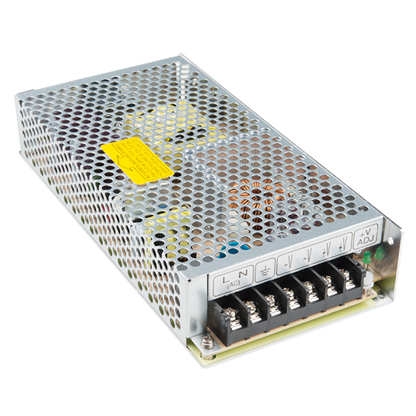
And I don't have one of these, I mean, I have one, but it is not for this voltage.
Either way I will have to wait for another fricking month until I can actually test some things out.
And yes, I can only spend 300 brazilian bucks per month.
Highly Porous Heater:
Since I already have all the materials to make this one, I'm still highly confused about the ratios I need for this thing.
I should've had thought this through (history of my life), because I'm pretty sure I would need to test various ratios for the perfect heater in this case.
And I just have a kilogram for each material.

I really should've paid someone to do this for me (like I had any money to do so)...
Although... I think it would be easier to make it porous if I used alcohol or the like...? Well, I will test it out on both cases, I bought more than enough anyway...
I also tried to search for electric steam generators that uses silicon carbide as porous heaters, but I had no sucess until now. If I could find a single article talking about it, I could've spared around 100 brazilian bucks...
By the way, Sucrose is just common sugar, I definitely didn't just waste 60 bucks on buying a chemical grade Sucrose without checking it first. Definitely not, this would be very stupid of me.
Just now, after asking for 298398392398th time, chatgpt suggested me using salt. and then dissolve it in water... And paraffin wax...
I mean, WHY DIDN'T I THINK OF THAT BEFORE?!
I could just have used carbon fiber as the heater...
In any way, here are some of the ratios I will be testing:
- In the first try I will go with the gut, I will measure the amount I have for each material first and then adding it to a small pot until it "looks right", then I will measure the materials again so I know how much I used for the mixture.
- Then I will try to use a ratio suggested by ChatGPT:
26% of sodium silicate
32% of silicon carbide
21% of graphite
19% of sugar. - Next I will try using a ratio suggested by BingGPT:
20% of sodium silicate
40% of silicon carbide
30% of graphite powder
10% of sugar
Well, it seems my intentions of publishing the project log before testing things out actually worked out very well.
For example, Esteban pointed out that using a silicon carbide heater directly in contact with water is a no-go because it reacts with water at 500ºC.
When it reacts with water, it creates Methane gas and Silicon Dioxide, more known as Silica.
This means that if I were to actually use this thing on a steam generator, I would be talking with the angels, because this is literally a bomb.

This is fine.
In any manner, I will try to use only graphite on the porous heater instead of silicon carbide. Maybe I can make a furnace with the silicon carbide for melting other stuff, but for now...
By the way, I will have to wait another 2 months to be able to buy the carbon fiber to be used as the porous heater...
About the dielectric elastomer:
So, it just came to my attention that I don't need two electrodes.
The idea of a dielectric elastomer is that both electrodes attract each other due to reverse polarities.

However, if you make the electrodes fibers, and all the fibers have the same polarity, they will repel each other. Simulating a contraction.

And since you can easily transmit very high voltages and very low amperages through hundreds of kilometers without much loss.
Plus, you don't need make complex stacks:

However, it also comes with many problems:
How to control contraction? How to predict contraction? How much force can the fibers take before failure and/or fatigue?
Electric motors continue to be the kings of reliability and pretictability.
Off-topic:
Well, like I said before: I need to figure out a way of making the direct contact electric motor.
The problem is that this design is so utterly alien to traditional electric motor design that I don't even know how to start it, I gave the idea of using hypocycloidal drives whre the teeth were the electromagnets. I still think it would be the best option, but I'm simply not qualified enough to figure out how to do it.
For example the only way I was capable of thinking on how to make dual pole teeth would be like this:

Of course, assuming the north and south pole would interact with anything outside of the stator. And then, even if I made all the dozen of teeths on both stator and rotor like this, how I would organize them on the 3 phases of the motor?

So... I think I will be forced to do the conventional way (as shown below), but wobbly just like in the example above:
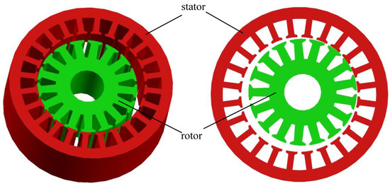
But I mean, what would stop the rotor from just rotating on the axis instead of wobblling as intended...?
While looking around I found this thing:

Source: https://visforvoltage.org/comment/77084
Way simpler to make and it still has direct contact, both rotor and stator have the same amount of poles...
Another problem on either idea is the phase quantity and sequence of activation. The best I could think of was individually activate and/or reverse each pole with a program and sensors... But the phase and wiring configurations have been used for decades (if not centuries).
Example:
What would be the ideal phase of this thing?
I really need help with this...
I THINK I can calculate somewhat how this direct contact motor could produce both as torque and RPM.
In resume, I will just pretend the electromagnets are piston heads rotating a crankshaft. The stroke of each electromagnet is 0.5mm, and as such, the crankshaft will have that same radius.
Only 2 are working, one attracting and other repelling. For such thing, I will try to use the force of the holding electromagnets for this estimate. As such, there will be 4 electromagnets activating at time.
So, a 50kg electromagnet consumes 10 watts, so 4 of these consumes 40watts. Since stacked electromagnets don't add force, then it would be 100 kg of force in total.
So, accordingly with the torque calculator, I would have 0.5 newton meter (I'm already not liking where this is going). And accordingly to the torque and rpm to horsepower calculator, if it had 3000 rpm, it would output 150 watts of power while only consuming 40 watts.
So I would consume around 3.9 times less power. Not the 100 times less power I was hoping...
For example, if I had an electric motor that outputed 100 horsepower or 75.000 watts, I would consume only 34.4 horsepower or 25.641 watts.
This seems to violate the laws of physics, but do keep in mind that the human body consumes at maximum 300 watts in activities while the Atlas from boston Dynamics consumes 3000 watts.
From all the other crazy ideas, I think this one is the most reliable, safe and understandeable to work with.
(it almost makes me wonder if I even should have attempted on testing the other alterntives and wasted my money...)
On top of that I will still try to figure a way of using electrostatic current (high voltage low amperage) instead of the conventional ones, essentially making every pole a capacitor.
Not because of I want to make something special or anything like that, it is simply because electrostatic electricity goes pretty well in any kind of high resistance material, unlike conventional currents, which needs copper wires.
I'm broke and I can't be buying copper and custom laminations whenever I like it or not. Simple as that.
The only electrostatic motors I could find were these two:
As expected, there isn't much information o the subject, only claims by patent owners.
As far as I could understand, it works just like conventional motors in the sense that it has 3 phases and the rotor has positive and negative poles.
The problem is that I don't know how much torque and rpm it makes per watt of power, they simply don't care about showing these things...
Plus, it seems like a weird option to use copper as the conductive material, specially since it can suffer passivation during prolonged exposure to high voltages...
I guess that since these are PCB plates it is reeeeally cheap to make them.
I think I found them:

Source: https://www.sciencedirect.com/science/article/abs/pii/S0304388620301212
This one is awfully familiar with the first "electrostatic" motor that I've posted up there.
Of course, it is a "Corona Discharge Motor", not electrostatic, if the current is flowing it is not static anymore.
But, as shown in the graphs on the article itself, it has a really low efficiency and a really low power usage.
In fact, it only has a few miliwatts of power.
This guy made and tested his corona discharge electric motor, and the results really meet up.
Discussions
Become a Hackaday.io Member
Create an account to leave a comment. Already have an account? Log In.
hey also doesn't silicon carbide react with water at very high temperature?
Are you sure? yes | no
Oh... I didn't know that... Thanks for telling me, I could actually die, you saved me (literally).
Are you sure? yes | no
oh god!!! well i'm glad you get to continue the project (and your life!!) :^)
Are you sure? yes | no
hey are you sure that PSU doesn't just take power from the wall socket? like 220v AC? I have a similar one for 5V, i just took apart some unwanted electronics and used the plug. (tho... make sure it works for 220v... the one in the picture shows L and N, which are normally used in north america as they only have a single live wire, instead of in south america where both wires are live)
Are you sure? yes | no
The one I bought was a cheap one from Aliexpress: https://youtu.be/EP9uKFeOwPQ
Are you sure? yes | no
ah, never mind i misunderstood
Are you sure? yes | no