 mircemk
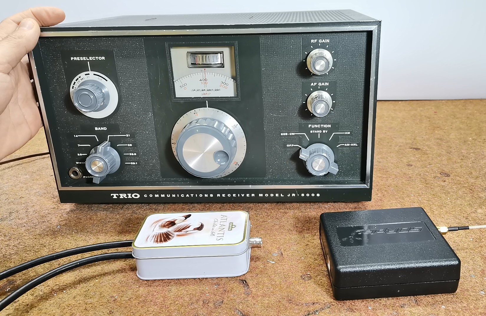
These days I came across an old Trio JR-500S ham radio receiver that was selling for $50 and bought it. According to the data I found on the internet, the device was manufactured in 1966 by the company "Trio", which after 1986 was known as Kenwood Corporation. At the time it was produced, it was advertised as a high performance communications receiver made especially to cover the amateur bands between 3.5 and 29.7 MHz.
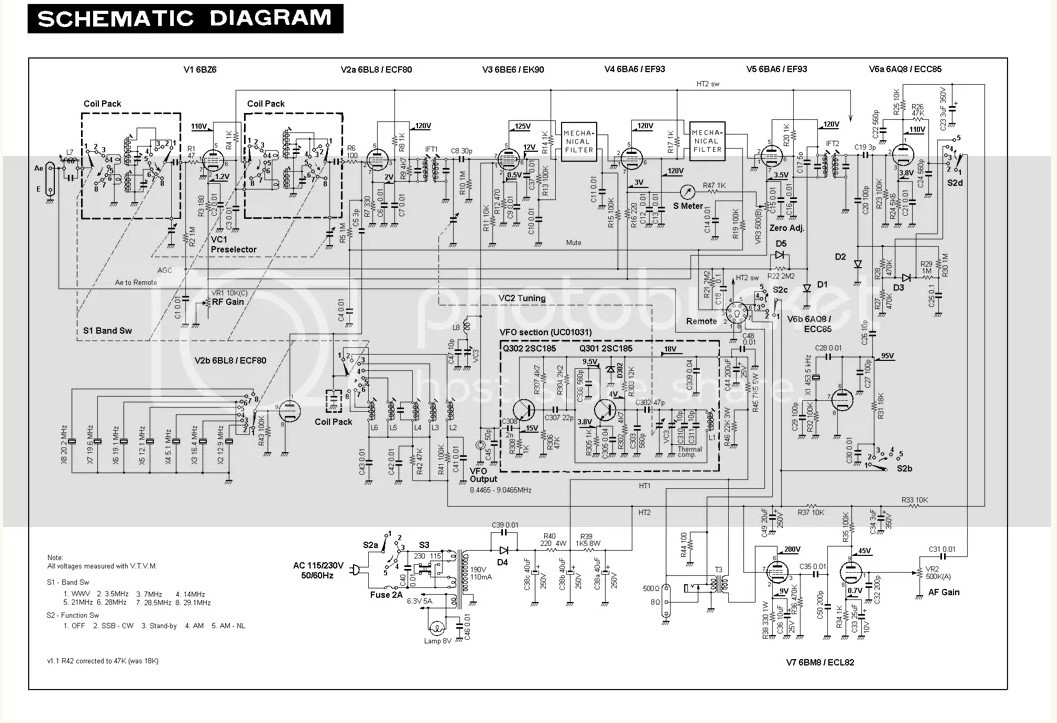
And, as always, after the first power-up the receiver did not work even though I received assurances from the seller that the device was fully functional. At first glance, the radio is in excellent condition, the interior was full of dust and visually I concluded that it has not been serviced or modified until now, which is a great sign. After that I detailed cleaned it, and immediately proceeded to find out the problem. After a quick check according to the circuit diagram that I downloaded from the Internet, I discovered that there is no anode voltage on the Tubes.
If you want to make a PCB for any electronic project, PCBway is a great choice for you. PCBway is one of the most experienced PCB manufacturing company in China in field of PCB prototype and fabrication. They have a large online community where you can find a Open Source projects, and you can also share your project there. From my personal experience I can tell you that on this community you can find many useful projects with alredy designed PCBs, from where you can place an order directly.

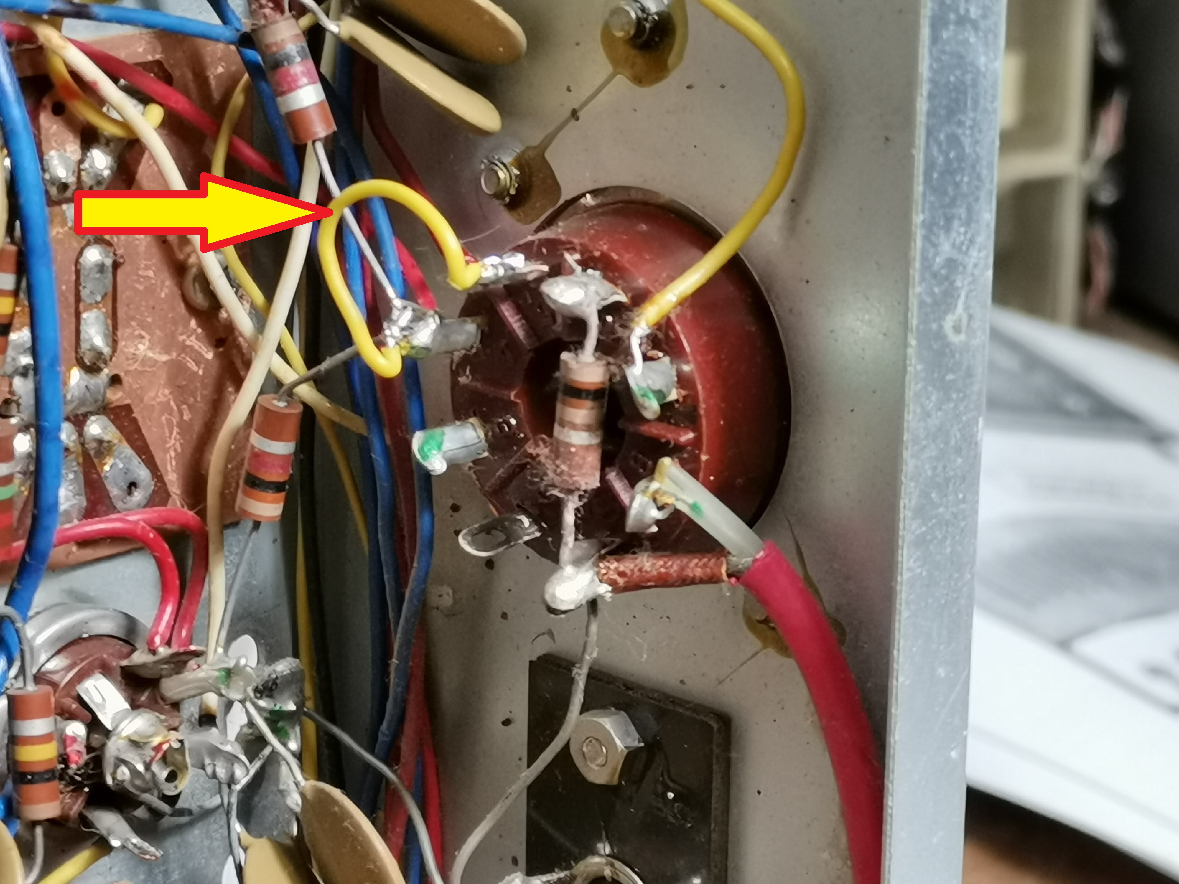
After that I found that this voltage was coming to the "remote" connector that serves to control the radio via a transmitter. It was then clear to me that the seller had used the radio together with a transmitter, so I connected the anode voltage to the Tubes by soldering a jumper as shown in the pictures.
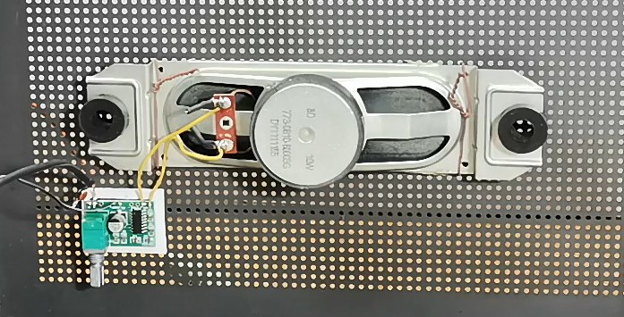
After that, the receiver worked immediately and the first sounds were heard on the small speaker that the previous owner had connected to the output. I don't know for what reasons, but the sound was desperately weak, so I instantly installed a cheap 3 watt class D amplifier board and bigger Speaker, right after the preamplifier on the 6BM8 tube, specifically after the C35 capacitor.
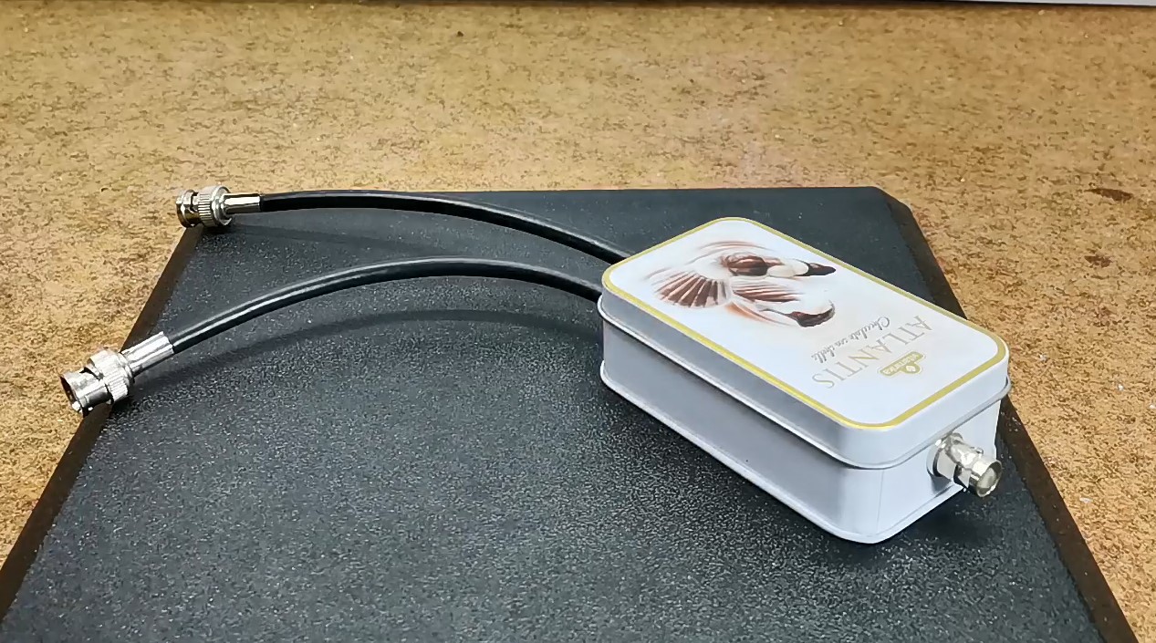
For testing the shortwave area I will use antenna splitter that I have made before, which is very simple to make and gives excellent results. In one of the following videos I will describe how to make it.
Also, I will use equal conditions (antenna) for both receivers, which in this case is a home-made "Loop on Ground Antenna" LoG , which I made according to the instructions of Matt Roberts (KK5JY.net),immediately after purchasing the radio. I want to say just a few words about this wonderful antenna.
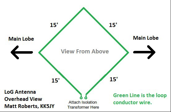
My home is located in a less-than-friendly RF environment surrounded by large buildings on all sides, but luckily I have a small yard where I placed the 15 feet square antenna right around the trunk of a large tree, installed directly on the surface. I still can't believe how good features has this antenna. First of all, the construction time is less than an hour, and from the material, you need any insulated wire of suitable length. I have installed several types of antennas on my roof, including Mini Whip, long wire antenna with antenna tuner, small loop active antenna, but the last LoG antenna is definitely my favorite. The signal-to-noise ratio is simply amazing, thanks to the fact that there are no active signal amplification components. With this antenna, I receive signals that I couldn't even think about until now, so I especially recommend you, if you have a little yard space, to try it.
And now let's connect the two radios mentioned in the title, and briefly compare the features. For more reliable results, I will try reception in several areas, during the day and at night.
And finally, a short conclusion:
Obviously, no real comparison can be made, considering that...


 Chad Grant