Close
0%
0%

Man Cave Accessory : IRremote Volume Control

Impetus: needed to change the PC volume
from my Submarine-motif rack [across the cave].

Similar projects worth following
Components:
IRremote kit - ProtoSupplies.com
LPC1114 microcontroller - Coridium.us "Special - $10"
USB serial converter - various suppliers
lightweight RC servo - type 90G - arduino kit special
ACE hardware parts - light dimmer, basic light switch
electric PVC box, lid, 2 switch cover plate
small hinge (future) & duct tape (for now)
USB cable - for power ; proto-jumper wires

Software:
Ideas & some bits of code from ProtoSupplies
& Arduino projects/libraries & Internet
PLUS: Coridium's ARMBasic IDE - free

More Information Coming @ Coridium.us / Forum / Projects "Man Cave Accessory"

PLEASE:

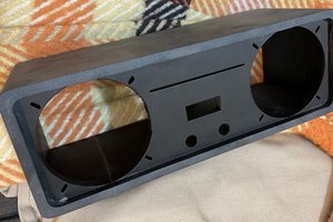
Isolate [cut}  traces to the Dimmer Switch [USB power} and the Dimmer Potentiometer

(I also removed the main AC power wires - for more room in the box)

.

I orientated the the standard light switch such that in sends the proper

signal to the microcontroller IO pin when it is pointed at the IR detector,

This switches from Analog Pot input to controller to the IR input to be decoded.

.

I used the Dimmer Switch to turn on/off the USB power to the microcontroller.

Of course, I had to carefully cut into the USB cable and solder some extension

wires up the to Dimmer/Switch contacts.

  • 1
    IR decoding

    This is for the NEC codes that the IRRemote transmits.
    The Arduino Library has coding/timing for the other brands.
    The use of Interrupt timing was garnered/modified from the
    Arduino code
    .
    I used the falling edge of the signal from the detector
    to create an Interrupt.  The ISR (Interrupt Service Routine)
    grabs the system time [in millisecs - ms] and puts it in
    an array.  - just falling edges.
    '
    Then the array is scanned from the end to the beginning,
    {so the math is easier - for me} to get the time differences
    between the ending/falling edge of the pulses of the IR coding sequence that NEC uses.  I then manually decoded
    the 0's and 1's - oh, watch out that NEC transmits the LSB first and the final is the MSB {another reason to start
    from the end of the timing array- imo}

  • 2
    Glitches

    I added another cap (capacitor)to the 5v line, - the servo motor induced a lot of false signals

    to the IR decoder chip.  I also put a .01 (?) cap on the decoder PCB also.  This reduces

    most of the interference.

    In the picture you may have noticed an object on top of the microcontroller.

    That is a 6 pin header soldered to the long leads of the cap, then inserted the leads

    into the PCB power connector - I ran out of places to put the (proto)  jumper cables/wires.

View all instructions

Enjoy this project?

Share

Discussions

Similar Projects

Does this project spark your interest?

Become a member to follow this project and never miss any updates