 mit41301
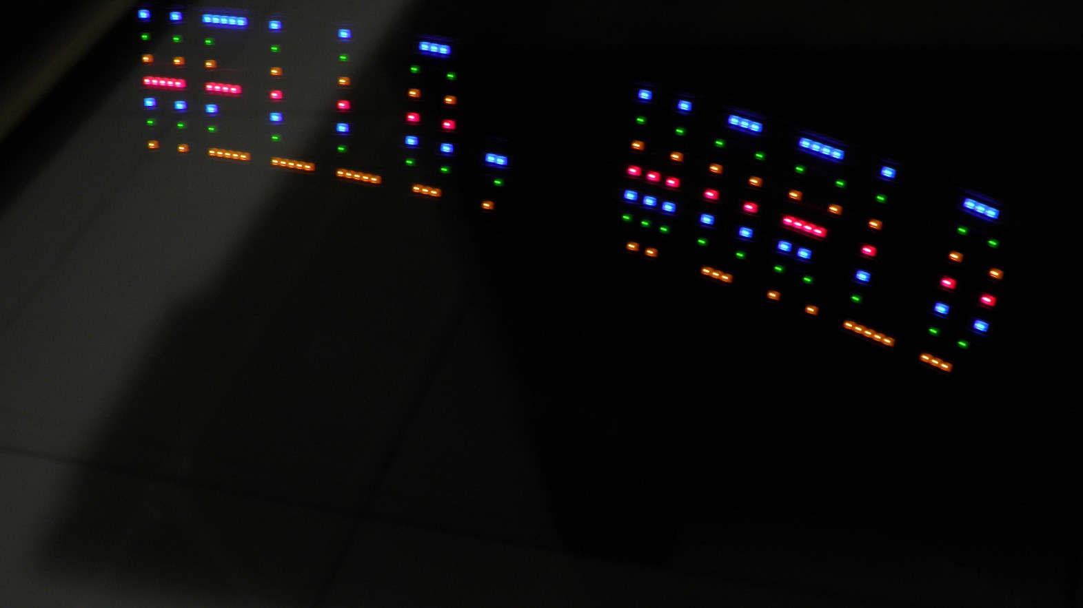
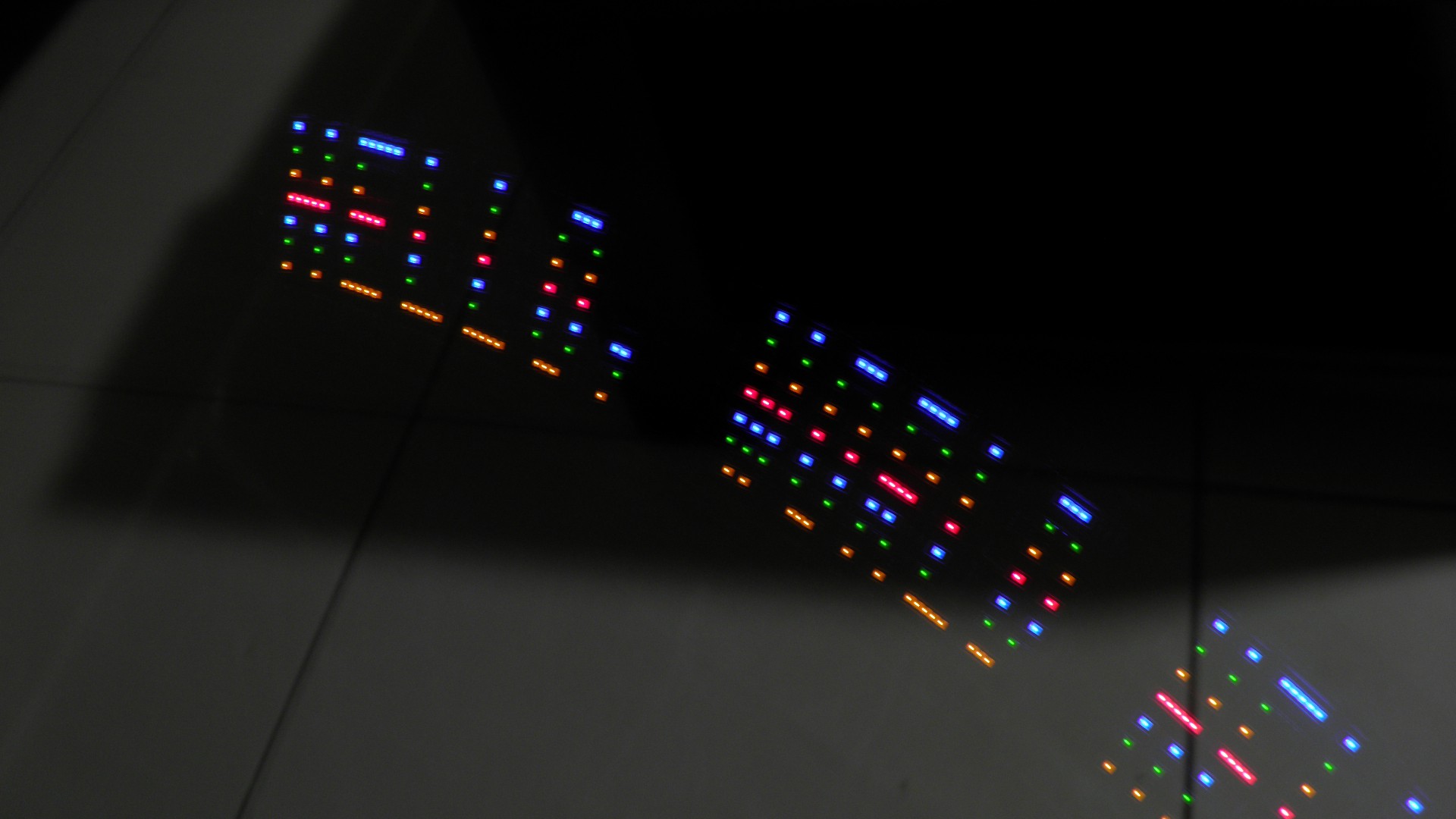
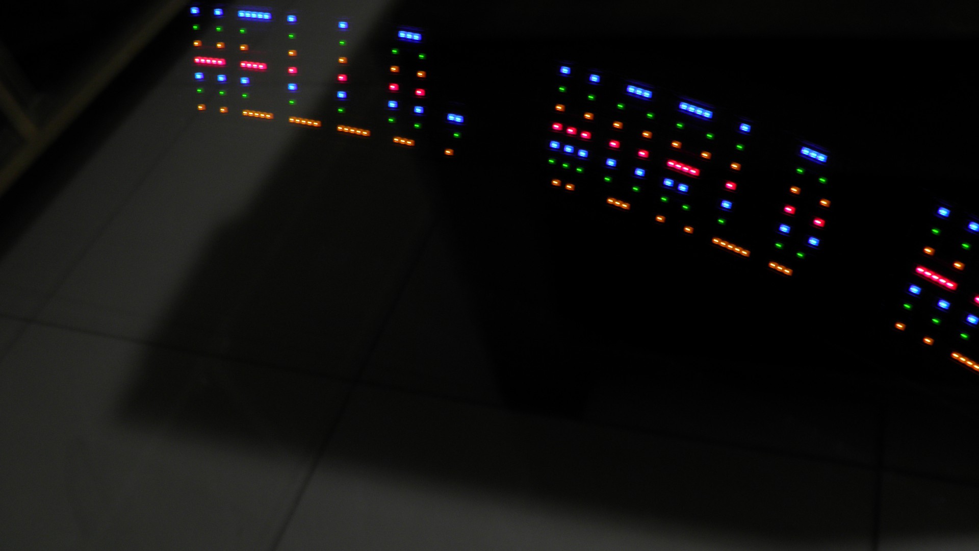
Most of the CPLD or FPGAs having both Configuration Flash Memory (CFM) and User Flash Memory (UFM). This simple and fun project explains how we can utilize the UFM and adding a simple binary counter can be used to display messages using POV.
This idea can be very easily implemented in any programmable logic device having both CFM and UFM.
The UFM is user as character ROM generator and simple binary counter implemented can be used to read the ROM and output the ROM content into any I/O pins or LEDs.
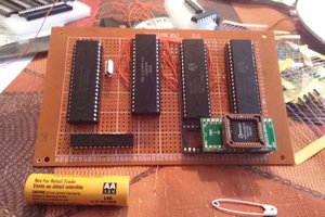
HARDWARE USED:

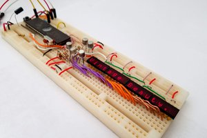
LAYOUT
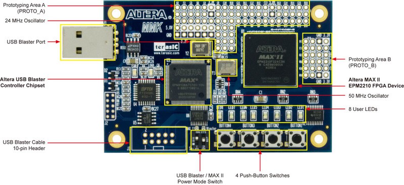
The board uses 50MHz Oscillator for CLOCK source and there are 8 LEDs available onboard.
This idea can be implemented on any MAX II, MAX V or MAX 10 family devices. We need 9 I/O pins for implementation.
8 pins for LED and 1 pin for CLK input.
LOGIC:
The display message is stored in the UFM memory as parallel ROM and the parallel ROM content is accessed using a parallel binary counter. So if the binary counter is enabled and running, the counter starts counting and if we connect the 8 consecutive bits of the counter output to the UFM parallel ROM memeory, then each ROM location content is available to external interface or LEDs for display. After overflow the cycle starts again.
We can create simple SCH and need not to familiar with any of the HDL!
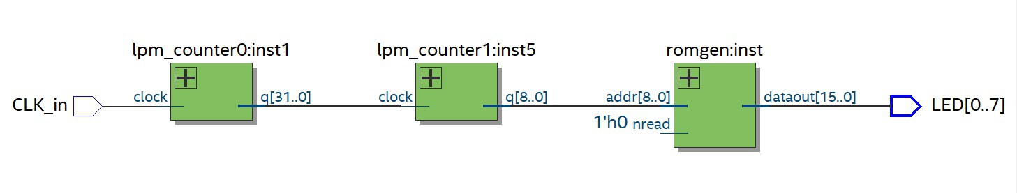
SCH:

The project was created using Quartus 18.1 Lite version and the design files are available in Github repo.
The parallel ROM is generated using altufm_parallel Megafunction. Please read and understand the attached UFM user guide from Intel FPGA.
The counter is designed using parameterized counter megafunction. The lpm_counter megafunction is a binary counter that features an up, down, or up/down counter with optional synchronous or asynchronous clear, set, and load ports. Intel FPGA recommends using the lpm_counter function instead of any other type of binary counter.
The counter is implemented in two stages for simply to adjust the ROM readout rate. Depents on the user Clock Oscillator Frequency, user can easily change the tap of the first counter to match the reasonable readout rate to get POV effect. User can still change the angular or linear speed of the LED to get optimum POV effect.
RTL
Now the user can load the ROM character table into the .mif file. An ASCII text file (with the extension .mif) that specifies the initial content of a memory block of ROM, that is, the initial values for each address.This file is used during project compilation and/or simulation. You can create a Memory Initialization File in the Memory Editor, the In-System Memory Content Editor, or the Quartus II Text Editor.
For Easy entry of mif we can create a Excel file for easy editing and correction.
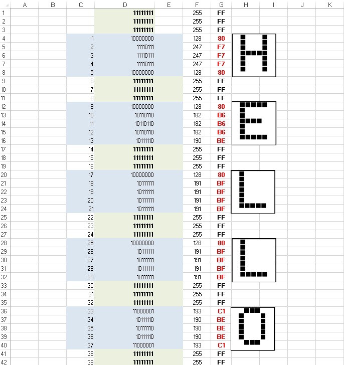
Quartus supports different radix entry for easy data manipulation.
Just enter the generated data of your entry into .mif file. Specify the mif file name in the megafunction wizard while creating the altufm parallel so that it will we included during compilation.
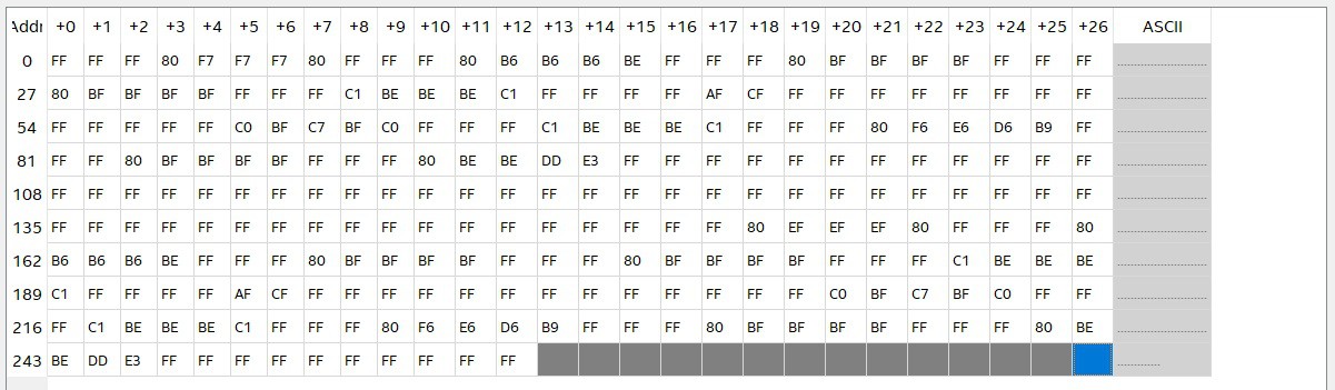
we can view or edit and save the mif window
Depends on SOURCE or SINK condition of the output to lit the LEDs we can invert the outputs by lpm_inv megafunction instead of inverting the ROM data bits. lpm_inv function is just NOT GATE. Or we can manually add NOT gate in each output pins connected to LEDs.
The ROM data and LED's LSB and MSB should match in the same order.

 Ethan Durrant
 zpekic
 Michael Wessel