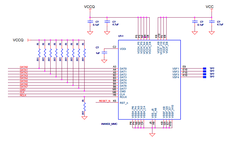
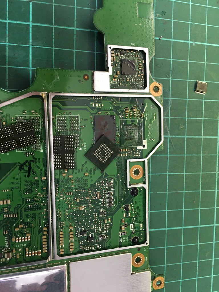
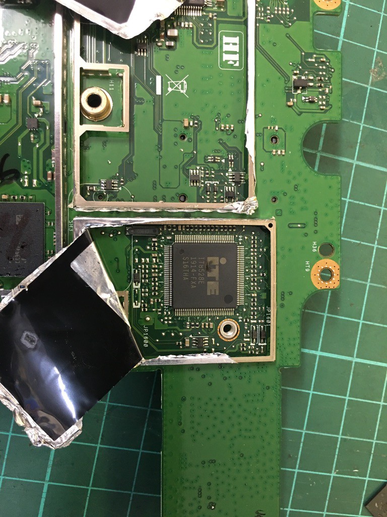
• power part 2

    Saabman02/13/2023 at 11:16 0 comments

    Reading through the data sheet in a bit more depth it does mention that VCCQ can operate at either 1.7-1.95V OR 2.7-3.6V now that simplifies things some what. I was starting to consider adding a 1.8V regulator to the mix but it loks like I can run it all off the 3.3V rail. Though the Data sheet does have a bit of a criptic Note "Device operation under 3.3V VCCQ is limited to Max 1 hour. " I take that to mean if I run it at 3.3 V I can only run it for a max of 1 hour. That constraint I can live in I only need to make one image of the drive and I'm done. 

    Started pulling some decoupling caps off the board to reuse direct on the chip - damn some of them are tiny - thank God for microscopes - must get better tweezers though.

  • Power requirements

    Saabman02/12/2023 at 12:05 0 comments

    Ive been working through the Data sheet to make sure Ive git all the connections I need. The data and clock lines seem somewhat straight forward but the power rails are a little more complex.

    According to the data sheet VCCQ is 1.8V and VCC is 3.3V the data sheet even provides a Reference schematic which I think will be safestto follow - though I will not be making a PCB for this but just dead bugging it. The plan is to solder the decoupling caps straight to the balls on the chip. She aint going to be pretty but as long as it works :-)

  • SD card Pinouts

    Saabman02/11/2023 at 12:14 0 comments

    SD card Pinout

    1. DATA3
    2. CMD
    3. VSS1
    4. VDD
    5. CLK
    6. VSS2
    7. DATA0
    8. DATA1
    9. DATA2

    eMMC Pinout

    A3. DATA0

    A4. DATA1

    A5. DATA2

    B2. DATA3

    M5. CMD

    M6, CLK

    the trick bit now is the connection of the power lines and provide supply decoupling. Thankfully I can remove caps from the original board and the plan is to solder them directly to the power pins of the eMMC chip. This is going to be ugly but it only needs to work long enough to extract the data.

  • eMMC removal

    Saabman02/10/2023 at 20:46 0 comments

    Got to have a go at the removal of the eMMC chip and so far successful. WIth some hot air the chip came away nice and cleanly.  I had a few practice goes with the RAM chips and got the technique nailed by the time I did the eMMC chip.

    Prior to me getting my hands on it my brother had sent it to a "profesional" data recover service but they couldnt extract the data as they suggested something like what ever caused the unit to fail in the first place was preventing them accessing the eMMC. When I get my hands on a PCB I pliek checking out what chips are on the board and look up their specs and just for my own entertainment. And this board was no different. there was the usual RAM chips and GPS module from uBlox then i uncovered a large device with a small burn hole in the face of it. The IT8528e is a power maagement IC and having a big hole in it isnt going to help anything. Punch IT8528 into duck duck go and the first thing that comes up is 


    https://www.aonemobiles.com.au › product › ite-it8528vg-fxo-power-management-ic-surface-pro-4

    ITE IT8528VG FXO Power Management IC (Surface Pro 4)

    Description. This is a replacement ITE IT8528VG FXO Power Management IC for the Surface Pro 4. This PMIC can fail leading to a common 3.3V rail being pulled low/shorted.


    Well I reckon that would be the problem - a $14 PMIC would have brought the trimble to a halt and prevented an in circuit data recovery - I suspect if that was replaced in the first instance my brother wuld still have a working trimble with all his data intact..

  • Where's the data stored

    Saabman01/30/2023 at 10:39 0 comments

    So  from a quick look at the board it appears the data is stored in a Sandisk 128GB  eMMC chip SDINADF4-128G