 Maximiliano Palay
Components
If I hadn't made it clear by now, let me say I haven't ever seen one of these in person, neither know how they work. I can only make assumptions looking at their construction and functionality.
With this little knowledge, I'm listing the components I want it to have and the reason for each.
- Microcontroller. The lamp needs brains, a CPU. While a full fledged SBC would be possible, I believe it's overkill. We don't need many interfaces and an OS to make this work, not to mention it consumes more power, for nothing.
- RGB leds. This is the core, its lamps - if you didn't notice. I'm thinking something cylindrical. Perhaps getting RGB LED rings seems like a good option.
- A vibrating motor. I'd like to add a vibrating feature and being able to notify with vibration, just like a smartphone.
- Encoder with pushbutton. As previously mentioned, I like the idea of a simple interface with a rotating knob. The pushbutton integrated into the knob is a great characteristic for increased control capabilities.
Without thinking much on the construction, I believe we can make a structure-less friendship lamp with these components. We might need a few electronics components such as transistors/resistors/etc, but we'll see that when we know exactly which components we're using.
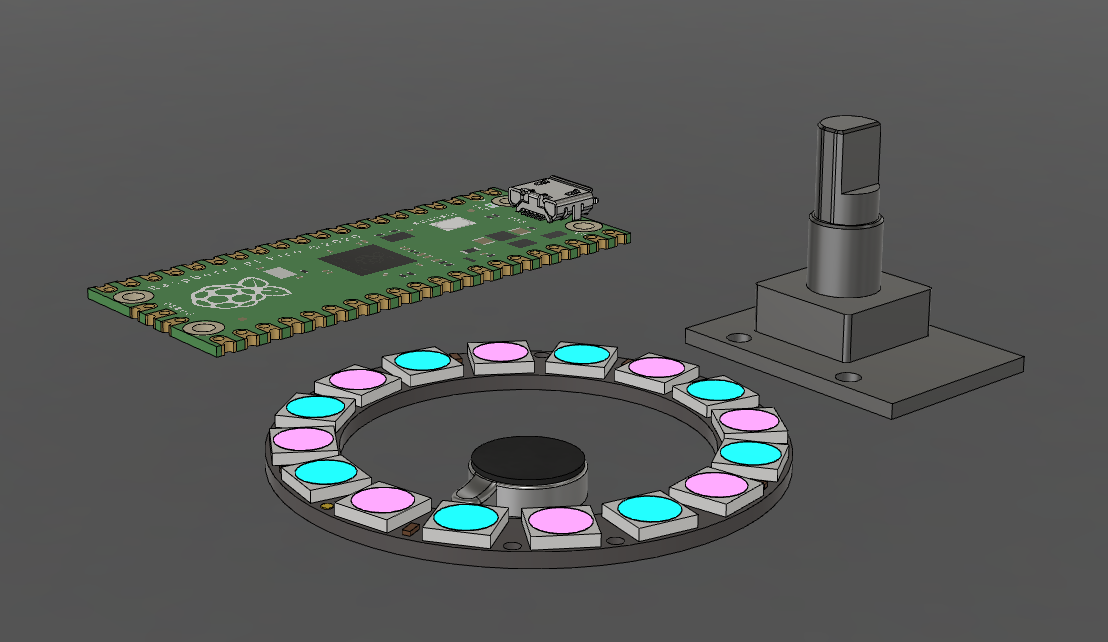
I usually have an idea in mind, so I know what to look for. In this case the microcontroller is a RPi Pico W which I previously acquired, and this project would serve as the first attempt at using it. The RGB leds are Adafruit's popular Neopixel rings, with 16 RGB LEDs, they pack some extreme brightness. The vibrating motors are cheap "coin cell vibration motors", just 10mm in diameter x 3mm high. Encoders are simple Arduino-compatible optical rotary encoder modules with 20 positions per turn and a pushbutton. I'll do a breakdown of the cost, bought everything on Amazon.
[$ = USD]
- RPi Pico W bought 3 x $30 ($10 each)
- Vibrating motors bought 10 x $12.76 ($1.28 each)
- Encoders bought 5 x $8 ($1.6 each)
- Neopixel RGB 16 LEDS 2 x $24 ($12 each)
This comes to a total cost of ~ $25 per lamp, only in electronics. We're still missing the construction (mostly resin and filament).
CAD design
My Fusion360 student license is about to expire, so this might be my last project on the platform, we'll see.
The first step towards designing this was getting the components models. GrabCAD has proven to be extremely useful in this kind situations, and that is where I got the Pi Pico and the Neopixel ring models. Always check that the models you download reflect the components you're using. In my case, the neopixel ring model is less than 1 mm different than the ones I have, but that is enough to make it not fit.
You might be asking yourself about the encoder and the vibrating motor, I didn't fin a model for those, so I got my caliper and started taking measurements.
With all the components ready, it was time to arrange them and create the structure which would hold everything together.
I envisioned a cylindrical shape, with every component located on a fixed base, and a rotating knob on top. The rotating knob would be part of the outer shell, so if you looked at it, you wouldn't know its a knob. I got inspired by my Xiaomi monitor light bar's remote. There were two options for the light ring: face up or down. I went with the latter. I know the lamp will be used on a white table, so it might as well help create a cool effect. Further, if I don't want the individual leds to be visible, I have to be quite precise about the distance between the LEDs and the diffuser (at least the minimum distance). This distance would mean more volume as well. Facing down, the LEDs aren't directly facing anyone, so this wouldn't be an issue. The power input would be the Pico's USB port, so it had to be correctly placed with a tidy opening.
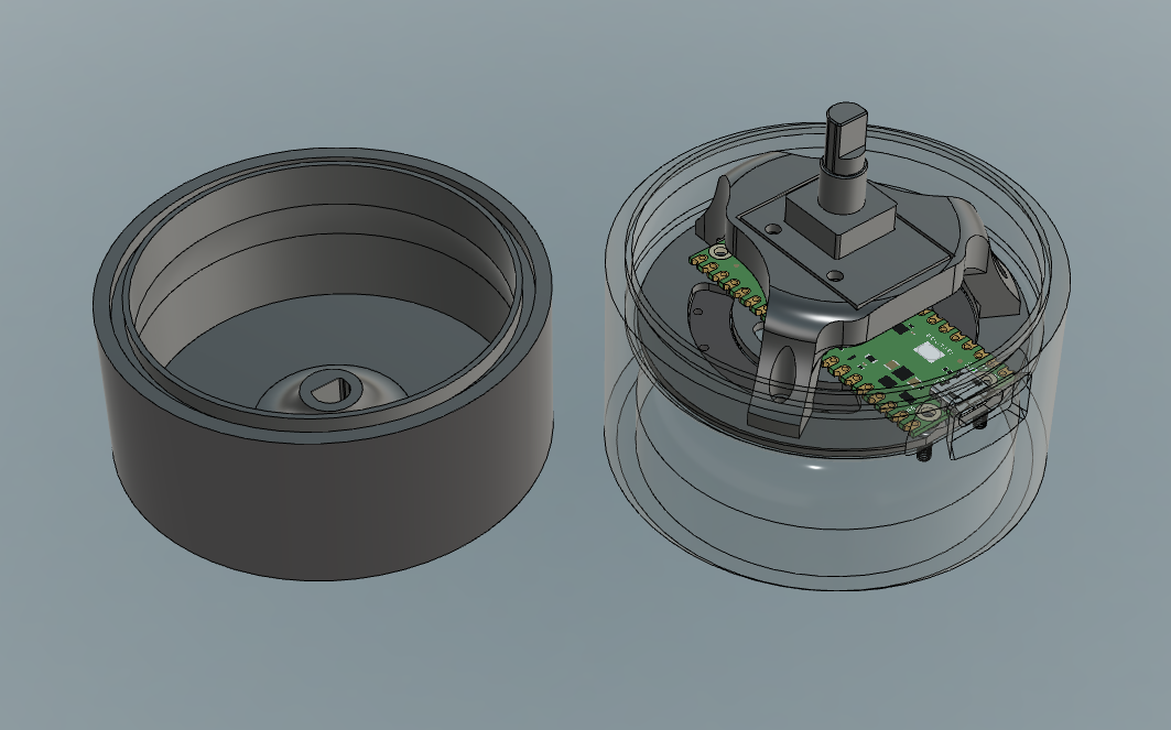
I began with the base, the placement of the LED ring and the vibrating motor, and then a bit of a stack design. A plate holds the LED ring & the motor in place, and has openings to allow for cables to go through and absorb less heat. On top of this plate lies the Pico, with two screws that fix it onto the base (these go through the plate), two screws which fix it onto the mid plate and a slot opening that leaves the USB port accessible. The encoder is then mounted in top of all, leaving the knob centered over the base. It's all held in place by M2 screws, and the M2 threads were directly printed on the base. You might be able to visualize this much better than I am able to explain on the following video.
There is some clearance between the Pico and the encoder for two reasons:
- leave some room without obstructing the antenna
- buffer space in case we need to add some more electronics (resistors/transistors)
At some point I considered adding a bearing to mount the rotating shell on. It's not ok to leave the alignment and structural strength to the encoder, but well, if it works this way who really cares. Engineers tend to overcomplicate things, I don't want to.
There's a few renders available on the gallery of this post.
Discussions
Become a Hackaday.io Member
Create an account to leave a comment. Already have an account? Log In.