If you have hard-time 3d printing stuff and other materials which i have provided in this project please refer the professionals for the help, JLCPCB is one of the best company from shenzhen china they provide, PCB manufacturing, PCBA and 3D printing services to people in need, they provide good quality products in all sectors
Please use the following link to register an account in JLCPCB
Pcb Manufacturing
----------
2 layers
4 layers
6 layers
PCBA Services
JLCPCB have 350k+ Components In-stock. You don’t have to worry about parts sourcing, this helps you to save time and hassle, also keeps your costs down.
Moreover, you can pre-order parts and hold the inventory at JLCPCB, giving you peace-of-mind that you won't run into any last minute part shortages. jlcpcb.com/RNA
3d printing
-------------------
SLA -- MJF --SLM -- FDM -- & SLS. easy order and fast shipping makes JLCPCB better companion among other manufactures try out JLCPCB 3D Printing servies
JLCPCB 3D Printing starts at $1 &Get $54 Coupons for new users
One of the simplest interfaces for an Arduino project is a push button switch. It can easily be added by connecting one side of the switch to ground and the other side to one of the Arduino’s digital input pins. Hold the input pin HIGH, either by using a resistor or the microcontroller’s internal pullup, and that’s all you need. Pressing the button will send the input pin LOW, and you can detect this change within your sketch to provide functionality for the push button.
_TIbnN9aRNA.png?auto=compress%2Cformat&w=740&h=555&fit=max)
Add a Resistive Keypad
This is a really elegant solution, and it only takes one analog input.
With this arrangement, a group of push buttons are connected to different points within a resistor array, that itself is connected between the reference voltage and ground.
When a push button is activated it causes a voltage to be sent to the analog input. As each push button is on a different leg of the array it will have a unique corresponding voltage. Your sketch can read the value of the A/D converter and use it to determine which button was activated.
This is a good solution for applications that only require a few push buttons, add too many buttons and you run the risk of inaccuracies due to reference voltage fluctuations or resistor tolerances.
But it certainly is a viable choice, and we have used it before in the article about using LCD displays. The LCD display shield has a group of push buttons wired up in this exact fashion.
_V0TXYpX1eo.png?auto=compress%2Cformat&w=740&h=555&fit=max)
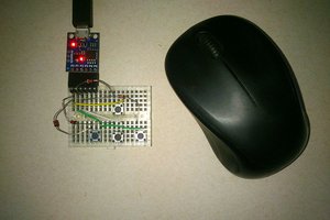
Add a Matrix Keypad
This is the solution we will look at today.
A matrix keypad is a group of switches connected in an X-Y, or row-column, matrix arrangement. Pressing a button will connect a row with a column, and we can then scan the array to determine which button was pressed.
By arranging the push buttons in a matrix as opposed to connecting them directly to input pins we can usually reduce the amount of wiring. Commercial matrix keypads are inexpensive and readily available, which simplifies the wiring even more.
This is a great solution, with the following caveats:
- You need at least six pushbuttons. Fewer than six defeats the wiring advantages, as six pushbuttons will require a 2 x 3 matrix for a total of five wires. A larger number of keys will increase the advantage of using a matrix.
- You don’t require users to press two buttons simultaneously. The keypad solution will only accept one input at a time.
- You’ll need to use a software routine to determine which button was pressed, this is in addition to the code you’ll need to write to actually do something once the keypress is received.
- You’ll still need a lot of inputs, not as many as discrete switches (providing you stay over five) but more than the resistive keypad or ASCII keyboard solutions. Once you exceed 25 push buttons you’re better off choosing the ASCII Keyboard solution.
In many cases, the matrix keypad still has a lot of advantages. And that’s what...
Read more »
 adi-miller
 Jinyu Meng
 danjovic
Totally useless project. You should have added even more link to JLCPCB