 Peter Sinclair
When designing something new there's always things you didn't know that come out during testing so it's incredibly important to put together a proof of concept to learn as much as you can as quickly as you can. The first version of the launcher was always meant to be a rough development platform to review the concept, electronics, and programming. To create this design I started with the system constraints/knowns. These can come in a variety of forms: capabilities, physical, financial, manufacturing process limitations, etc.
Financial
- Relatively low cost but feature rich (Below $1k)
- No hidden part costs (ie. I used these $500 motor controllers I already had so they are free!)
Manufacturing Process
- 3D printed parts wherever possible
- Non-printed parts should be easily manufactured using minimal equipment
Physical
- Easy to transport
- Battery powered
- As small as possible
- As safe as possible
Miscellaneous
- Easily available parts for others to duplicate
Capabilities
- Good court coverage
- Trajectory control
- Rotation control
- Programable shot pattern
- Adjustable shot calibration
Launching Wheels
I started with the Baddy wheel design as it was proven so would be safer/faster than designing one from scratch.
Using that geometry as the known we can calculate a rough estimate for the required rotation speed to perform a smash. A good smash is 100m/s and the wheel diameter is 104mm.
Where omega is in rad/s, V_tan is in m/s, and r is in meters.
This gives a rotation speed of about 1923 rad/s. We can convert to rotations per second by dividing by (2*PI), and multiply by 60 to get the rotations per minute. This gives 18,364 RPM. Since this ignores many factors, such as slip between the wheels and shuttle, the real motor speed would need to be even higher.
For the wheel motors I wanted to use brushless motors such as those used on drones. These tend to be rated by kV which is the motors' unloaded RPM/Volt. Since I was considering using a common 11.1V 5000mAh 3S LiPo battery we can divide out the desired RPM by 11.1 to determine the required motor kV of 1654. In reality to achieve this smash speed we would need a much higher KV to account for the loaded motor speed, losses, and the voltage drop of the battery over the session.
However, if we then consider a drop shot of 10m/s we would only be at 10% of the motor's maximum speed. Since most brushless motors and ESC's without feedback don't operate well below 1/3 of their max speed we can't handle such a powerful motor, so let's start from the drop shot instead. At an estimated 10 m/s we'd need a kV of 165 RPM/Volt so if that was 1/3 of the motor's maximum it would have a kV of 495 RPM/Volt. Recalling all of the factors that result in this number being low I'd estimate we want to be above 600 kV.
In the end I selected a 750 kV motor which was close to the target value. I suspected that the large diameter form factor of the selected motor would have a stronger bearing to take the shock loading of the feeding sequence and provide higher toque compared to a smaller motor. Its short length also helped minimize the height of the launcher.
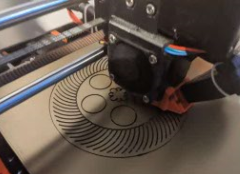
While I'd adopted the general wheel geometry from the Baddy project I needed one that could mount to the selected motor so for the initial testing I decided to try a complaint wheel 3D printed entirely out of PETG. This worked relatively well when a rubber band was glued around the outer diameter but the band failed quickly.
Trajectory / Rotation / Gripper / Pushers
In order to speed up design and reduce risk I eliminated the trajectory & rotation features from the preliminary build. While the force for the gripper & pusher is very low I settled on a two low cost 25kg servo motors with the intention of using them for all 4 controls in the final design.
For the catch/push arm I directly mounted it to one of the servo horns included with the servo.
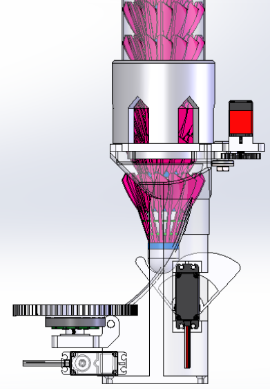
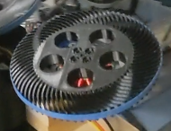
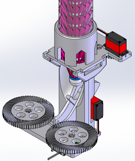
For the gripper I decided to use a simple printed pincer gripper with a gear train to drive it. This style of gripper would take up less space in the final build then many alternate designs. Eventually I changed the servo gear to one using spokes so that a jam would result in the gear breaking away instead of burning out the servo motor.

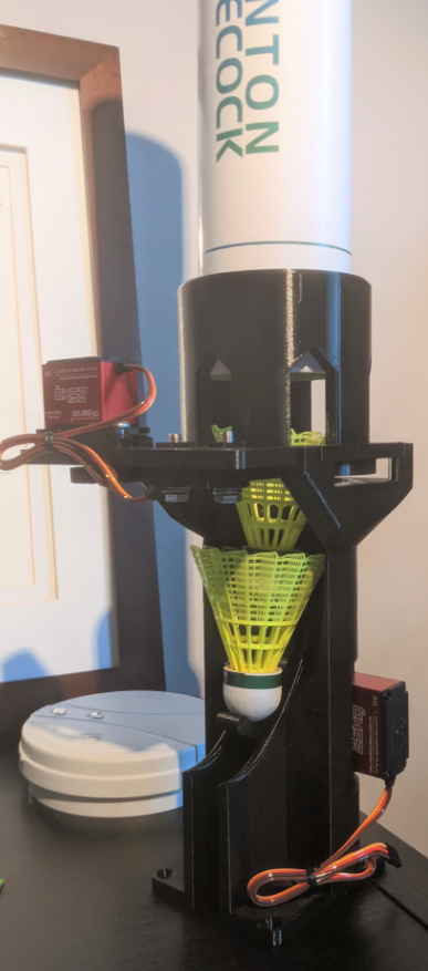
Launch Tower
For the initial test I wanted to keep things simple and avoid a full housing. The tower would have mounting locations for the servos, motor mount board, and hold the top assembly containing the pincer assembly.
Electronics
I considered a few options but eventually settled on an ESP32 development board for its low cost, wifi capabilities, and high pin count. It's very popular which means there are many libraries and resources to learn from.
For the brushless feed motors I settled on 30A ESC's. They needed to be low cost and have braking to slow down the motors quickly for safety.
To power the servos and feed the microcontroller I purchased a 3A 5V step-down module designed for hobby drones. I was trying to avoid a custom control board so chose external self contained modules wherever possible.
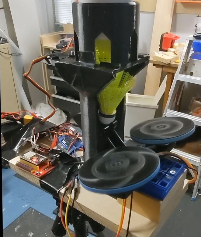
Completed Assembly
For the initial testing the tower was screwed down onto a wood board and mounted to a tripod. The electronics were attached on the back of the board for the testing.
Discussions
Become a Hackaday.io Member
Create an account to leave a comment. Already have an account? Log In.