 Peter Sinclair
With version 2 of the application I decided on a radical redesign. Version 1 was very functional but it was hard to adjust the shots quickly. When a beginner player came to try it there was no way to reduce the difficulty without just limiting the shot pattern or reprograming all 9 shots. I wanted to fix these issues and make it a lot more friendly and so I came up with the idea to use a full interactive 3D interface. I'm working on implementing that but I'm very excited about what it allows.
This type of 3D view is often created with the assistance of a library, but I was concerned about trying to fit one onto the microcontroller so I decided it would be best to keep it as small as possible by writing it without any libraries. While learning about these options I came across 3D plot code from Frido Verweij which showed this was possible and laid the ground work I needed to proceed.
Check it out here:
https://library.fridoverweij.com/codelab/3d_function_plotter/3d_function_plotter_plainjs.html
That example was designed to show a single math function and only allow rotation of the view so there was a lot of work to make it work for this application:
- Added zoom and pan functionality (touch & mouse)
- Added plotting of lines, court plane, nets, launcher, shot positions, etc.
- Added shot markers and the ability to resolve & adjust their position on the court once it's rotated in the 3D view.
- Added the ability to create, modify, and clear shot sequences.
- Added Play/Stop button to start and stop the feed.
- Added full flight path modeling and velocity solving.
- & more.
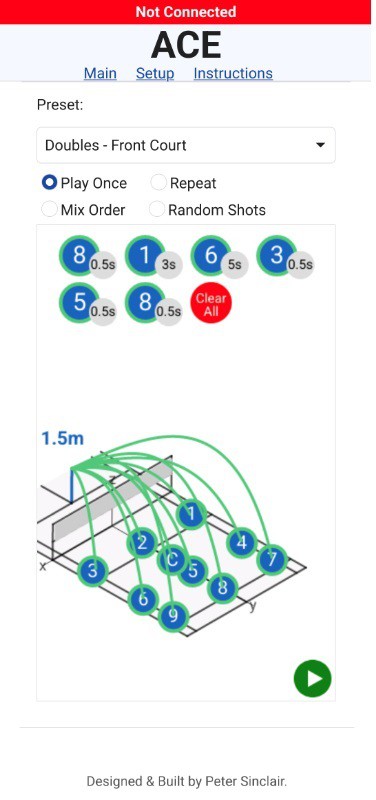
Main Page
Here the user will be able to adjust shot placement and create shot sequences along with all other controls needed to run the launcher.
The presets allow pre-population of the shots based on court size (Singles vs Doubles) and training type (Full Court, Front Court, Service Return, Out of Bounds, Locked Rotation, etc). After they are populated the shots can be adjusted directly on the court if needed.
As with the version 1 interface, the user can select the play type: play once, repeat the shot pattern continuously, mix the order of the selected shots, or fully random. I may remove the fully random shots as I think the user should add all 9 shots with desired delays based on shot type then mix up the order of those.
To add a shot to the pattern the user simply clicks on the shot indicator on the court in the desired shot order. The delay will be based on the currently set default but can be adjusted by click on the delay value in the pattern. The shots themselves can be removed by clicking on the number in the pattern or by using the clear all button. If the shots are not landing where expected or the user wants to make a change they can do so directly on the 3d view. More information on that can be found below.
Shot placement can be adjusted by simply dragging the shot marker. Green flight paths & markers indicate that a valid solution was found by the solver while red means the shot placement cannot be achieved based on the current constrains. This is dependent on the selected trajectory, current physical head rotation, and the maximum angle that can be imparted by the feeder wheels.
Currently the solver is set to allow 15 degrees of angle to be imparted by mismatching the two feeder wheel speeds. In the below graphic the head has been set to be rotated to +20 degrees, but the angle needed for the shot is close to 0 degrees. Since the feeding wheels can only impart 15 degrees of correction the shot cannot be achieved (5 degrees off).
Using the wheel correction to impart angle can be a valuable tool to allow the launcher to be deceptive (up to +-15 degrees) or to allow a locked mode where the head does not rotate at all to avoid telegraphing the next shot.
The flight trajectory is based on a paper from Hugo Janton from 2019 where he analyzed the Baddy launcher. His algorithm plots the flight path given an input velocity and angle. I've implemented a simple method that calculates the distance from the launcher to the shot landing point then uses that to find the input velocity. While I'm sure this could be solved directly I opted for a simple brute-force method:
The algorithm takes a target distance and lower and upper velocity as it's inputs. The distance the shuttle would travel at the lower and upper velocity is calculated. If the target distance is not within the lower/upper range the shot cannot be achieved. If it is within the range then the average of the two velocities is computed and that shuttle flight distance is calculated. If that's within our acceptable shot accuracy then the shot is considered solved and that velocity value is returned. If it's not, we compare the mid-point distance to the target distance. If the target distance is greater we'll repeat the same process using the midpoint as the lower velocity. If the target distance is smaller we'll repeat the process using the midpoint as the upper velocity. We keep doing this until the desired accuracy is achieved then return that velocity.
Eventually we'll need to convert this velocity into wheel RPM's. With zero wheel imparted angle this should be fairly straight forward but with mismatched wheel speeds it will not be. There is a lot of work to do to see if Jugo Janton's model is accurate for the flight path and to develop a model for the wheel speeds given the required target velocity and imparted angle. At the moment I've only planned in a global velocity correction but I'm not sure if that will be enough. Do I need to have an correction on the wheel angle correction? The drag coefficient? We'll see....
At this point the UI is looking pretty nice but with such a major re-write all the firmware needs to be rewritten almost in it's entirety. So today it's just pretty pictures and a need to get back to work.

Discussions
Become a Hackaday.io Member
Create an account to leave a comment. Already have an account? Log In.